81
Installation Instructions
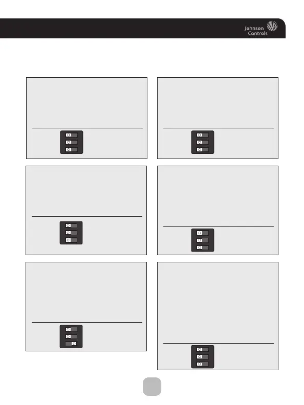
Sample Wiring Diagrams with Dip Switch Positions
Conventional Heating and Cooling Systems
Residential & Commercial 1 Stage Heating
with no Fan.
2 Wire, Heat Only
The thermostat will not work with
2 wires. Pull new wire.
Residential & Commercial 1 Stage Cooling.
4 Wire, Cool Only
R
C
Y1
G
Residential & Commercial 1 Stage Cooling,
with 1 stage Gas Heat.
5 Wire, 1 Stage Cooling, 1 Stage Heat
24VAC Power
24VAC Common
1st Stage Heat
1st Stage Cool
Fan
Residential & Commercial 1 Stage Cooling,
with 1 stage Electric Heat.
5 Wire, 1 Stage Cooling, 1 Stage Heat
24VAC Power
24VAC Common
1st Stage Heat
1st Stage Cool
Fan
Residential & Commercial 2 Stage Cooling,
with 3 stage Gas Heat.
8 Wire, 2 Stage Cooling, 3 Stage Heat
24VAC Power
24VAC Common
1st Stage Heat
2nd Stage Heat
3rd Stage Heat
1st Stage Cool
2nd Stage Cool
Fan
R
C
W1/O/B
Y1
G
R
C
W1/O/B
Y1
G
R
C
W1/O/B
W2
W3/AUX
Y1
Y2
G
24VAC Power
24VAC Common
1st Stage Cool
Fan
GAS/EL HP
O
GAS
B
ELEC
GAS/EL
123
ON
HP
O
GAS
B
ELEC
GAS/EL HP
O
GAS
B
ELEC
GAS/EL HP
O
GAS
B
ELEC
GAS/EL HP
O
GAS
B
ELEC
123
ON
Residential & Commercial 1 Stage Heating
with no Fan.
3 Wire, Heat Only
24VAC Power
24VAC Common
1st Stage Heat
R
C
W1/O/B
GAS/EL HP
O
GAS
B
ELEC
123
ON
123
ON
123
ON
123
ON
123
ON