ZFR1800 Series Wireless Field Bus System Technical Bulletin40
Using the ZFR Wireless USB Dongle
An LED on the ZFR USB Dongle is used to indicate connection status to a ZigBee
wireless mesh network and wireless communication activity by flashing while
wireless communication packets are transferring from the dongle to a ZigBee
wireless mesh. There is also a small pinhole button on the ZFR USB dongle that is
reserved for future features.
Setting ZFR Wireless USB Dongle Parameters in CCT
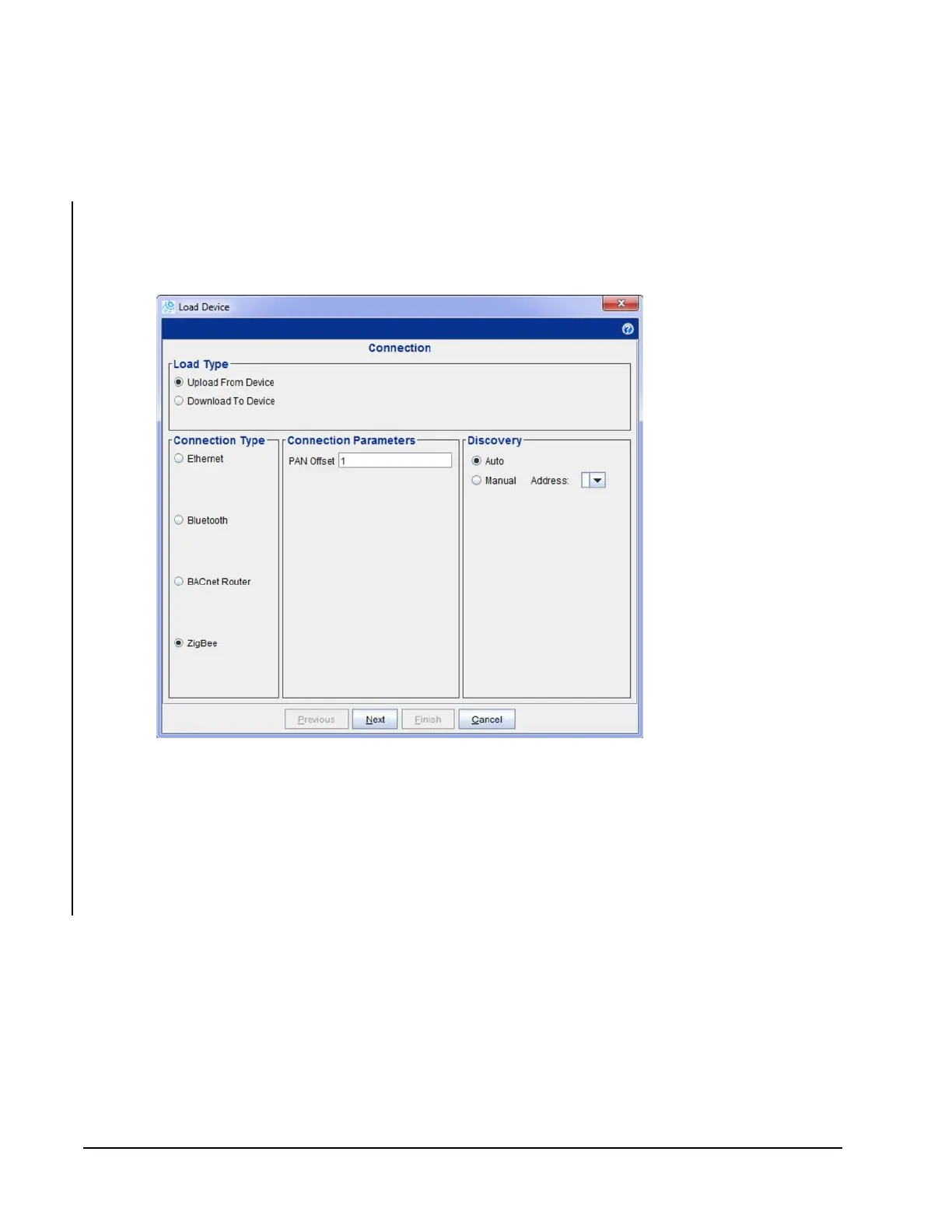
Use the Load Device dialog box in CCT to set ZigBee connection parameters.
1. Insert the ZFR USB dongle in an available USB port.
2. Because the dongle does not connect to the mesh at the ZFR1810 Coordinator,
you should locate the laptop near a router or repeater with an available address.
Depending on the mesh, you may need to relocate the laptop to another
location to connect to the mesh.
3. Select the ZigBee connection type.
4. Enter the PAN ID of the wireless mesh you want to join.
5. Click Next.
The ZFR USB dongle LED flashes rapidly (approximately three times a
second) until it successfully joins the mesh. The LED illuminates solid after
successfully joining the mesh. The LED flashes during communication with
wirelessly enabled field controllers.
Figure 15: CCT Load Device Screen