ZFR1800 Series Wireless Field Bus System Technical Bulletin74
Appendix C: Restricted Hallway Scenario
Using a linear or daisy-chain arrangement instead of a mesh is not recommended
because it can create a scenario where a single point of failure results in disrupted
network communications. Some installations require this linear configuration,
such as in a building wing or long hallway where signals need to cover long
distances, but building restrictions (architectural, appearance, owner preference)
restrict use of (or prevent installing) repeaters in hallways. This scenario often
requires extra repeaters, resulting in excessive address depths and an increased
number of signal hops.
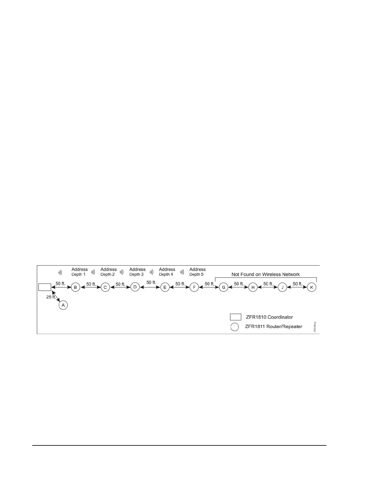
Figure 25 shows this sort of scenario. If you plan the wireless system only on the
basis of transmission distances and transmission hops, you might think that this
scenario should work, because there is no more than 50 ft between each device and
its neighbor and because the WRZ sensor associated with the ZFR1811 Router
labelled K uses 10 hops to transmit the signal to the coordinator. However, only
part of this system works because this network design ignores the limit of the
five-depth short address assignment. When a wireless mesh network forms, it uses
up to five layers in assigning short addresses required for network communication.
In Figure 25, the ZFR1811 Router labelled E is at Address Depth 4, and is the last
device that can assign a subaddress to an associated WRZ sensor. The ZFR1811
Router labelled F is at Address Layer 5; and although it can join the network, it
cannot assign an address to a WRZ sensor. The ZFR1811 Routers labelled G
through K do not get short addresses, and cannot join the mesh network.
The WRZ sensor associated with the ZFR1811 router labelled D can use four hops
to send the signal to the ZFR1810 coordinator. The ZCT scan may show five hops
because the network may route the signal through the ZFR1811 router labelled A.
Figure 25: Hallway Scenario