7 Configuration
60
Method
The standard method is the oscillation method, whereas the step response method is used specifically
in the plastics industry. With the oscillation method, the output level is set alternately to 100 % and 0 %,
which produces oscillation of the control variable. With the step response method, a step of a specified
size is made from the standby output. In both cases, the controller determines the optimum controller
parameters from the response of the actual value.
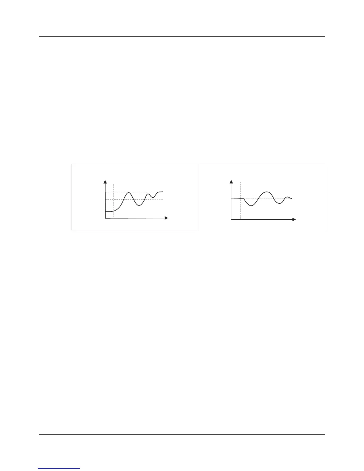
Optimization according to the oscillation method
In the case of a large control deviation between the setpoint value and actual value (for example, in the
startup phase), the controller determines a switching line around which the control variable performs a
forced oscillation during autotuning. The switching line is determined so that the actual value does not
exceed the setpoint value if possible.
In the case of minor control deviation (e.g. if the control loop is in a steady state during operation), oscil-
lation is forced around the setpoint value. Here, the setpoint value is exceeded in any case.
The controller automatically chooses between two procedures depending on the extent of the control de-
viation:
Optimization according to the step response method
Initially, a configurable standby output is produced until the actual value "settles" to a constant. This is
automatically followed by a configurable output level step (step size) to the control process.
Main applications of the step response method:
• Optimization immediately after "power on" during startup (considerable time saving, standby output
setting = 0 %)
• Control process does not oscillate easily (for example, extremely well insulated furnace with low
losses, long oscillation period)
• Actual value must not exceed the setpoint value
If the output level is known for the corrected setpoint value, overshooting is prevented with the fol-
lowing setting:
Standby output + step size ≤ output level in corrected state
The progression of the output level and actual value depends on the status of the process at the point
when autotuning starts:
Autotuning during the startup phase Autotuning during operation
x = actual value
S = switching line
w = setpoint value
t1 = start of autotuning
 Loading...


