61
7 Configuration
Optimized controller parameters
With both autotuning methods, the parameters for PI or PID controller structure are optimized according
to the configured controller type and the configured "Control structure" parameter: proportional band Xp
(P component), derivative time Tv (D component), and reset time Tn (I component).
The cycle time Cy and the filter time constant dF are also optimized.
The configured control structure is not changed by the optimization if it is a PI or PID control structure.
In all other cases, it is optimized to PID control structure.
For 1st order control processes, the parameters required for the PI control structure are optimized, inde-
pendently of the "Control structure" configured parameter.
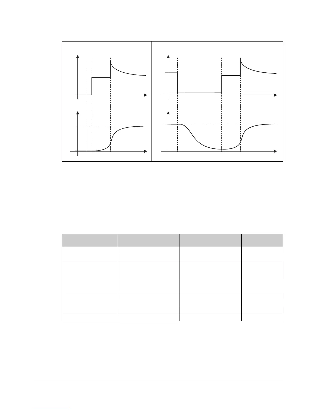
Autotuning during the startup phase Autotuning during operation
y = output level
y
S
= standby output
x = actual value
w = setpoint value
Δy = step size
t1 = start of autotuning
t2 = time of output level step
t3 = end of autotuning
Configured controller
type
Configured parameter Optimized parameters Optimized con-
trol structure
Two-state controller Control structure 1 = PI Xp1, Tn1, Cy1, dF PI
All other settings Xp1, Tv1, Tn1, Cy1, dF PID
Three-state controller Control structure 1 = PI
or
control structure 2 = PI
Xp1, Xp2, Tn1, Tn2, Cy1,
Cy2, dF; (Tv1/2 = 0)
PI
All other settings Xp1, Xp2, Tv1, Tv2, Tn1,
Tn2, Cy1, Cy2, dF
PID
Three-step controller Control structure 1 = PI Xp1, Tn1, dF PI
All other settings Xp1, Tv1, Tn1, dF PID
Continuous controller Control structure 1 = PI Xp1, Tn1, dF PI
All other settings Xp1, Tv1, Tn1, dF PID
 Loading...


