6
2 Installation
Installation notes
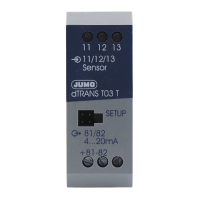
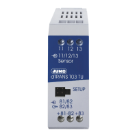
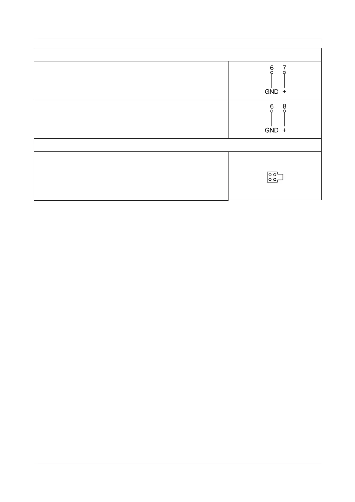
Digital outputs
Open-collector output 1
v See “Connection examples” on page 34.
Open-collector output 2
v See “Connection examples” on page 34.
Setup interface
!
The choice of cable, the installation and the electrical connec-
tions must conform to the requirements of VDE 0100 “Regula-
tions for the installation of power circuits with nominal voltages
below 1000V”, or the appropriate local regulations.
!
The electrical connection, as well as work inside the unit, must
only be carried out by qualified personnel.
!
Ensure that the instrument is completely isolated from the sup-
ply before carrying out work where live components may be
touched.
!
A current limiting resistor (safety function) interrupts the supply
circuit in the transmitter in the event of a short-circuit.
!
Avoid magnetic or electric fields, such as caused by transform-
ers, mobile phones or electrostatic discharge in the vicinity of
the instrument
1
.
A
The setup interface and the analog out-
put are not electrically isolated.
v See “Setup interface” on page 8.