1. Attach the grounding strap to your bare wrist and to a site ESD point.
2. Ensure that the power supplies are fully inserted in the chassis and the latches are secure. If only one
power supply is installed, ensure that a blank cover panel is installed over the second power supply
slot.
3. Locate the power cord or cords shipped with the switch; the cords have plugs appropriate for your
geographical location.
WARNING: Ensure that the power cord does not block access to device components
or drape where people can trip on it.
4. Connect each power supply to the power sources. Insert the coupler end of the power cord into the
AC power cord inlet on the AC power supply faceplate.
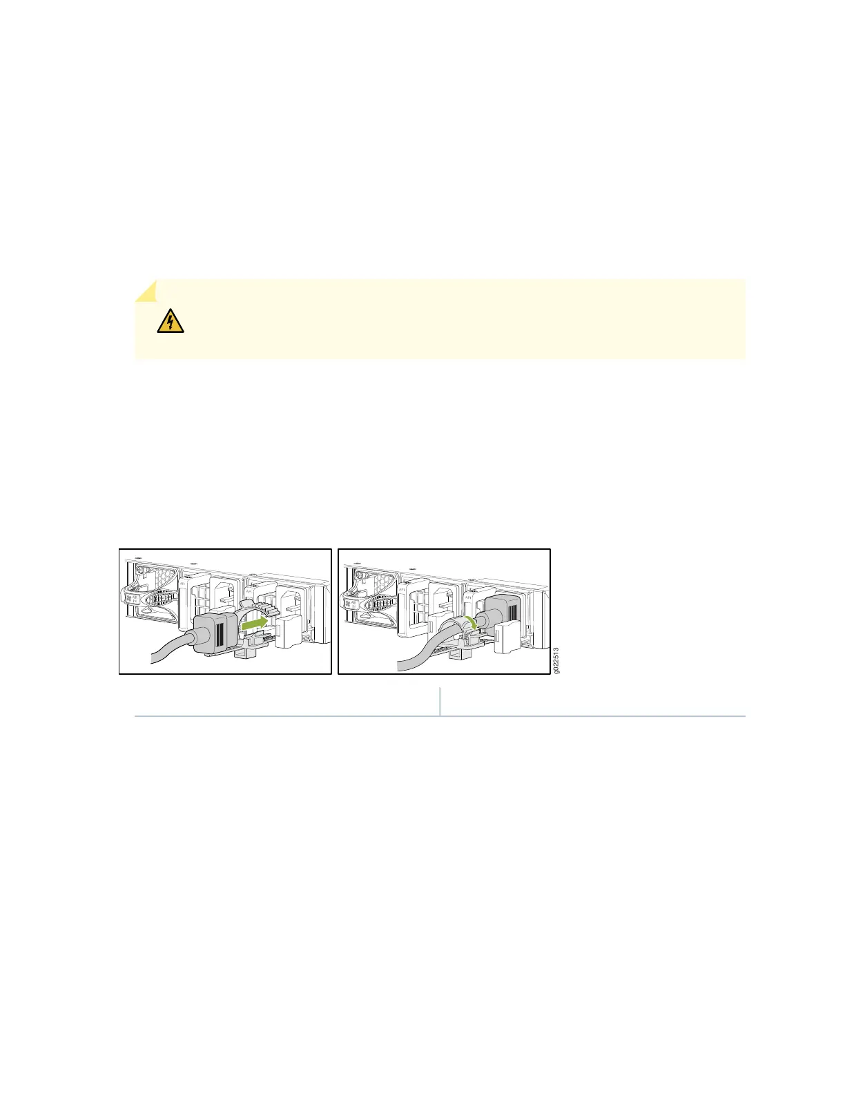
5. Push the power cord retainer onto the power cord (see Figure 36 on page 89).
Figure 36: Connecting an AC Power Cord to an AC Power Supply in an EX4650
1—Power cord retainer
6. The switch powers on as soon as power is provided to the power supply. There is no power switch on
the device.
7. Insert the power cord plug into an AC power source outlet.
8. Verify that the AC and DC LEDs on each power supply are lit green.
If the amber fault LED is lit, remove power from the power supply, and replace the power supply. Do
not remove the power supply until you have a replacement power supply ready: the power supplies
or a blank cover panel must be installed in the switch to ensure proper airflow.
89