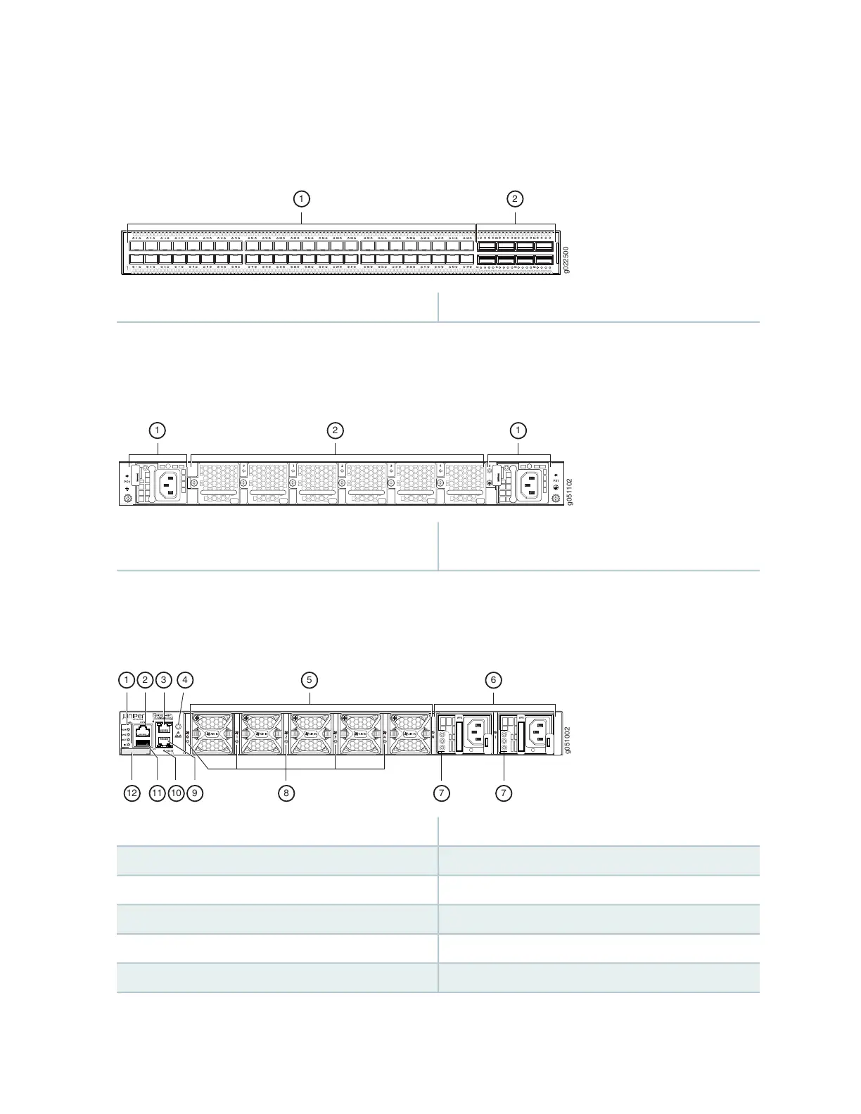
and Figure 6 on page 25 shows the front panel of a QFX5120-48Y switch.
Figure 6: Front Panel of a QFX5120-48Y Switch
2—1— QSFP portsSFP ports
Figure 8 on page 25 shows the rear panel of a QFX5120-32C switch with AC power supplies.
Figure 7: Rear Panel of a QFX5120-32C Switch with AC Power Supplies
2—1— Fan modulesAC power supply in slot 0, AC power supply in slot
1
Figure 7 on page 25 shows the rear panel of a QFX5120-48Y switch with AC Power Supplies.
Figure 8: Components on the Rear Panel of a QFX5120-48Y Switch with AC Power Supplies
g051002
1 3 4
5 6
2
12 11 10 89 7 7
7—1— Power Supply LEDsChassis Status LEDs
8—2— Fan Module LEDsConsole Port
9—3— RJ-45 Management Port (C0)RJ-45 Management Port (C1)
10—4— Reset ButtonESD Point
11—5— USB PortFan Module
12—6— CLEI LabelPower Supplies
25
 Loading...


