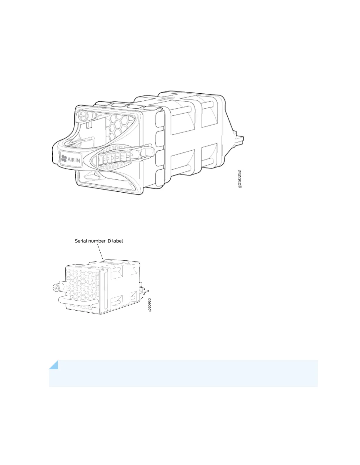
Figure 16 on page 31 and Figure 17 on page 31 shows the fan modules.
Figure 16: QFX5200-32C and QFX5200-32C-L Fan Modules
Figure 17: QFX5200-48Y Fan Module
You remove and replace a fan module from the FRU end of the chassis. The switch connues to operate
for a limited period of me (30 seconds) during the replacement of the fan module without thermal
shutdown.
NOTE: All fan modules must be installed for opmal operaon of the switch.
The fan modules are available in four product SKUs that have dierent airow direcons—FRU-to-port
airow and port-to-FRU airow On legacy switches or switches with LCDs, this airow is also called
31