EasyManua.ls Logo

JVC MX-GA77 User Manual

JVC MX-GA77
89 pages
To Next Page IconTo Next Page
Page #1 background imageLoading...
Page #1 background image
SERVICE MANUAL
COMPACT COMPONENT SYSTEM
No.22001
May. 2003
COPYRIGHT 2003 VICTOR COMPANY OF JAPAN, LTD.
MX-GA77
MX-GA77
Contents
Safety Precautions
Importance administering
point on the safety
Preventing static electricity
Disassembly method
Wiring connection
Adjustment method
Flow of functional operation
until TOC read
Maintenance of laser pickup
Replacement of laser pickup
Trouble shooting
Description of major ICs
1-2
1-3
1-4
1-5
1-18
1-19
1-23
1-24
1-24
1-25
1-29~42
Area suffix
J ------------------- U.S.A.
C ---------------- Canada
SP-MXGA77 SP-MXGA77CA-MXGA77
CD
1
DISC CHANGE
DISPLAY
CD
2
CD
3
TUNING
STANDBY
RANDOM
PROGRAM
DUBBING
REC START
/ STOP
CD REC
START
SET
CLOCK
/ TIMER
CANCEL
/ DEMO
SOUND
TURBO
TAPE A / B
REPEAT
PHONES
TUNING
COMPACT COMPONENT SYSTEM MX-GA77
ROCK
POP
CLASSIC
DANCE
HALL
STADIUM
S
O
U
N
D
M
O
D
E
V
O
L
U
M
E
EJECTEJECT
SUBWOOFER LEVEL
PRESET
STANDBY/ON
BEEP
MP3

Table of Contents

Question and Answer IconNeed help?

Do you have a question about the JVC MX-GA77 and is the answer not in the manual?
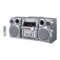
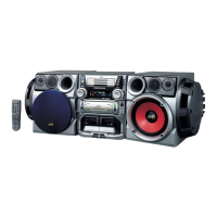
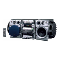
JVC MX-GA77 Specifications

General IconGeneral
TypeMini System
Speaker Type2-way bass reflex
CD PlayerYes
RadioYes
FM TunerYes
USB PlaybackYes
USB PortYes
MP3 PlaybackYes
WMA PlaybackYes
BluetoothYes
Remote ControlYes

Summary

Safety Precautions and Component Handling

General Safety, Fuses, and ESD Prevention

Covers general safety warnings, fuse specifications, and static discharge prevention measures.

Disassembly and Servicing Procedures

Main Unit Disassembly Procedures

Procedures for removing covers, CD changer, and front panel assemblies.

CD Mechanism Servicing

Steps for removing the pickup unit and other CD mechanism parts.

Speaker Unit Servicing

Steps to detach the side speaker and its panel.

Adjustments, Operation, and Troubleshooting

Wiring Connection Diagram

Visual representation of internal wiring and connections between components.

Adjustment Procedures

Calibration steps for tuner sensitivity, bias, and cassette deck parameters.

Troubleshooting Guide

Diagnostic steps for power, tuner, CD, and amplifier issues.

Technical Reference

Major IC Descriptions

Pin layout, block diagrams, and functions of key integrated circuits.

System Block and Schematic Diagrams

Overview of functional blocks and detailed circuit diagrams for major sections.

Exploded Views and Parts Lists

Lists of parts for general assembly, mechanisms, boards, and packing.

Related product manuals