DN112-06v02
JYE Tech - 19 - www.jyetech.com
Output of Captured
Data
DSO112A has two working modes. Normally it works in
Standalone Mode where captured data are displayed on LCD
panel as waveform. In situation where captured data are wanted
DSO112A can be set USB Scope Mode. Under USB Scope
mode waveform display on panel will be disabled. All captured
data are output through the SI.
To make the oscilloscope enter or exit USB Scope mode certain
commands are required. These commands must be sent to the
oscilloscope via the SI. All available commands are described
in details in the section “Commands and Their Returns” below.
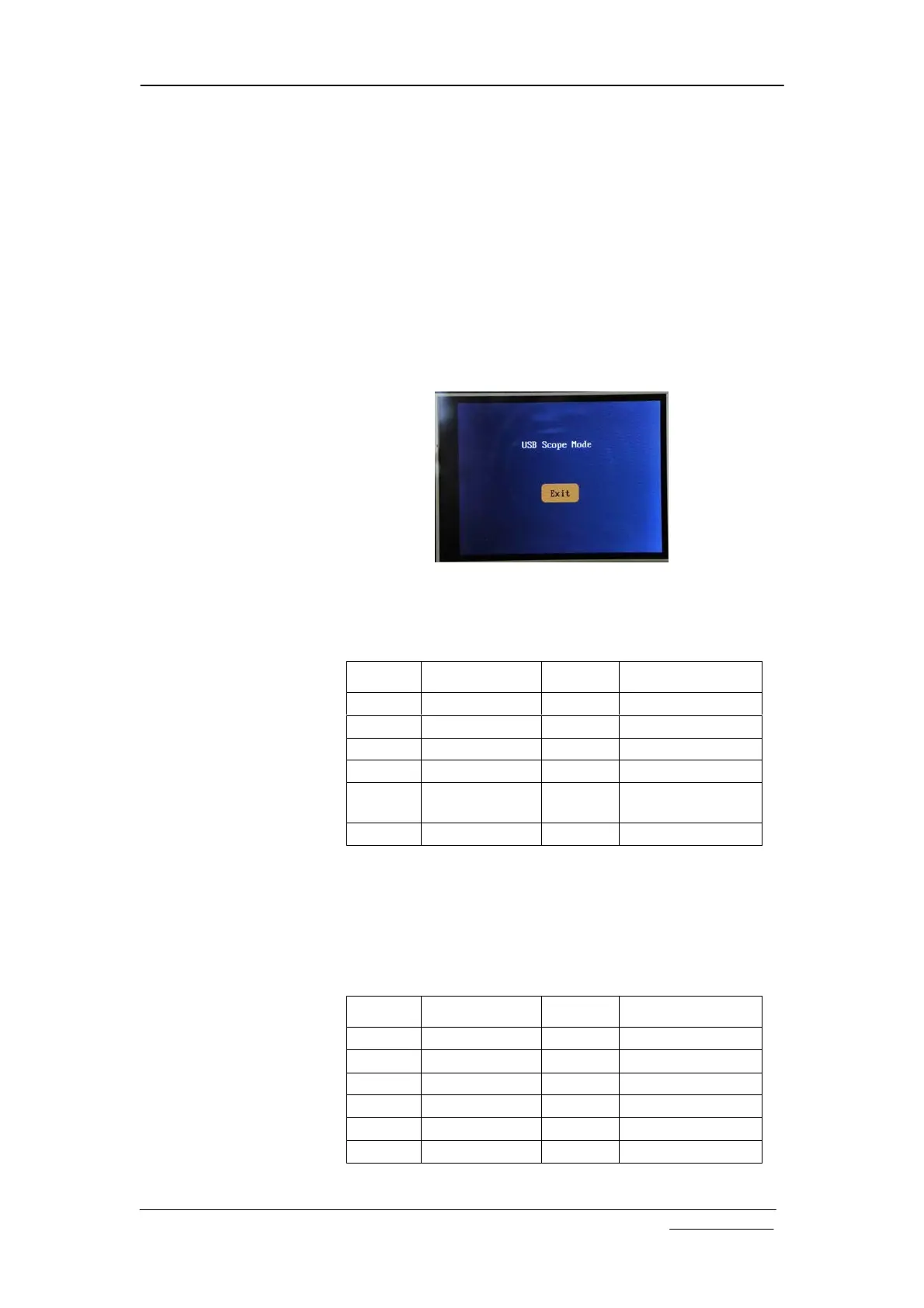
In USB Scope mode the oscilloscope panel will look like the
photo below. Touch the “Exit” button to return to standalone
mode.
When timebase is set to 20ms/div or faster the oscilloscope will
output captured data in blocks of samples. Each block contains
the whole buffer of data. The format of output is shown in the
table below.
Because record length can have different values the frame size
is variable.
When timebase is set to slower than 20ms/dic (i.e. 50ms/div or
slower) oscilloscope will output data in single sample. Each
frame contains only one sample. The format is shown below.
Offset Field Name Size Value
-1 Sync character
1 0xFE
0 Frame ID 1 0xC0
1 Frame Size 2 Record length + 8
3 Data Type 1 0x32
4 Captured data Record
length
Each byte for
one sample
RL + 4 Reserved 4
Offset Field Name Size Value
-1 Sync character
1 0xFE
0 Frame ID 1 0xC0
1 Frame Size 2 8
3 Data Type 1 0x33
4 One sample 1
5 Reserved 3