DN112-06v02
JYE Tech - 5 - www.jyetech.com
Most elements are self-explained in the figure. The following
are some further explanations for some elements.
Vertical Position Indicator
Indicating the 0V signal level.
Horizontal Position Indicator
This consists of a green bracket and a white rectangle inside
the bracket. The green bracket represents capture buffer size
and the while rectangle represents the viewed portion of
capture buffer.
Trigger Level Indicator
Indicating trigger level with reference to signal level.
Trigger Position Indicator
Indicating trigger position inside capture buffer which is
represented by the green brackets.
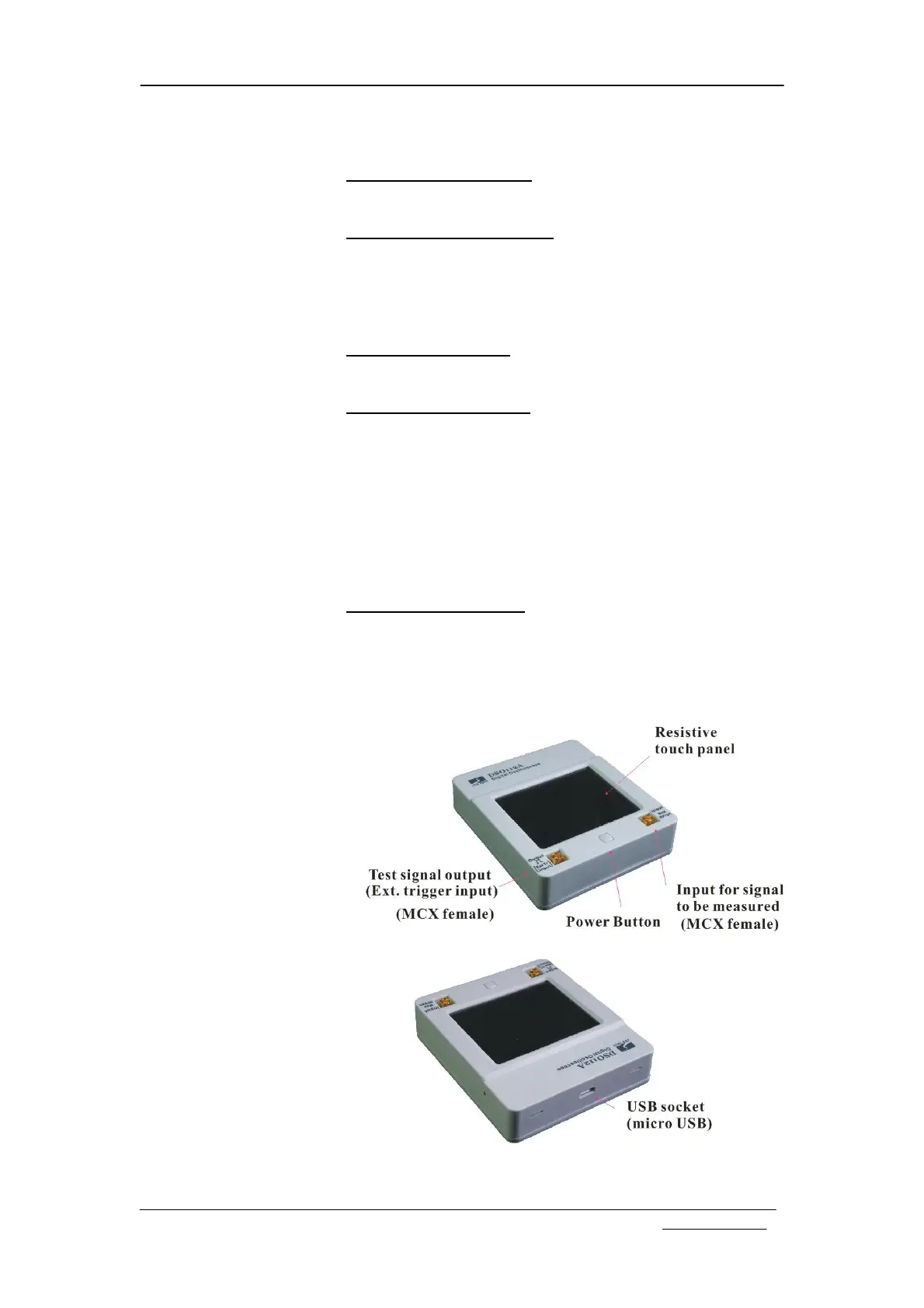
Connectors
The following figure shows the functions and types of DSO112A
connectors. Please note that the Test Signal Output connector is
dual functional. It becomes external trigger input when external
trigger is selected. The test signal output is disabled accordingly.
Test signal output will restore when external trigger is deselected.
Maximum Voltage Range
The maximum input signal voltage is 50Vpk.
The maximum external trigger voltage is 15Vpk.