Precondition The supply disconnecting device is switched off,
the device is locked off,
the absence of voltage has been verified.
1. Have an oil receptacle ready.
2. With the shut-off valve closed, insert the male hose fitting 6 into the hose coupling 9 .
3. Place the other end of the maintenance hose in the oil receptacle and secure it in place.
4. Open the shut-off valve 11 .
5. Slowly open the shut-off valve 7 in the maintenance hose and allow oil and air to drain com‐
pletely.
Pressure gauge on the oil separator tank indicates 0 bar.
6. Close the shut-off valve 11 and unplug the male hose fitting.
➤ Dispose of used oil in accordance with environment protection regulations.
Draining the oil from the thermostatic valve
A drain plug is provided to drain oil from the thermostatic valve. If the machine is connected to an
external heat recovery system, oil should also be drained from the heat exchanger at a suitable
point.
Precondition The external heat recover system is de-pressurised.
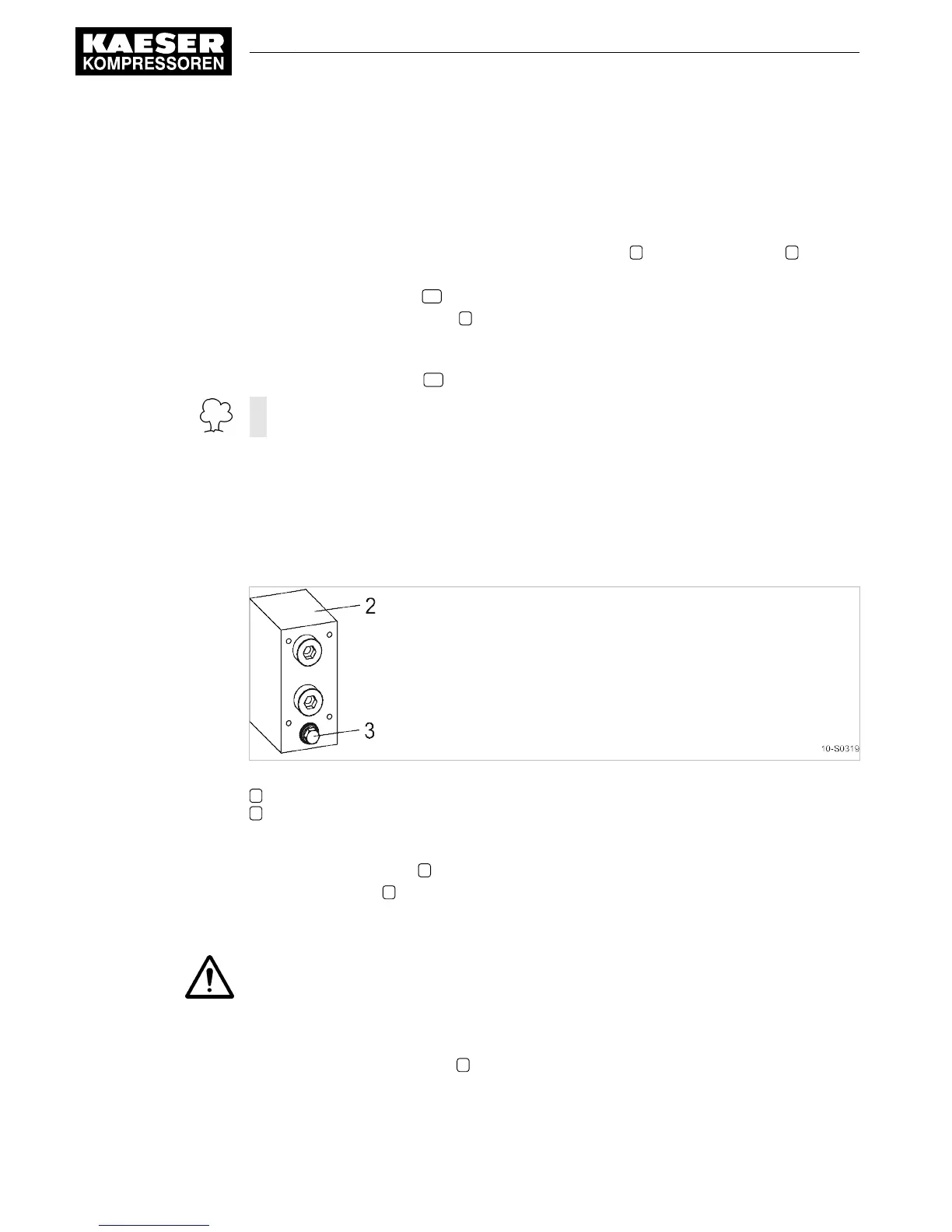
Fig. 28 Changing the cooling oil, heat recovery system
2 Thermostatic valve
3 Screw plug
1. Have an oil receptacle ready.
2. Remove the drain plug 3 and allow the oil to drain completely.
3. Replace the plug 3 .
Filling with cooling oil
1. WARNING!
Compressed air!
Compressed air and devices under pressure can injure or cause death if the contained energy
is released suddenly.
➤ De-pressurise all pressurised components and enclosures.
2. Slowly unscrew the filler plug 4 (see illustration 27).
3. Fill with cooling oil.
4. Check the filler plug and ring seal for damage and screw the plug back in again.
10 Maintenance
10.15 Changing the cooling oil
76
Service Manual Screw Compressor
ASK T SIGMA CONTROL BASIC 9_5717 20 E
Option W1

 Loading...