Installation
6 --- 35
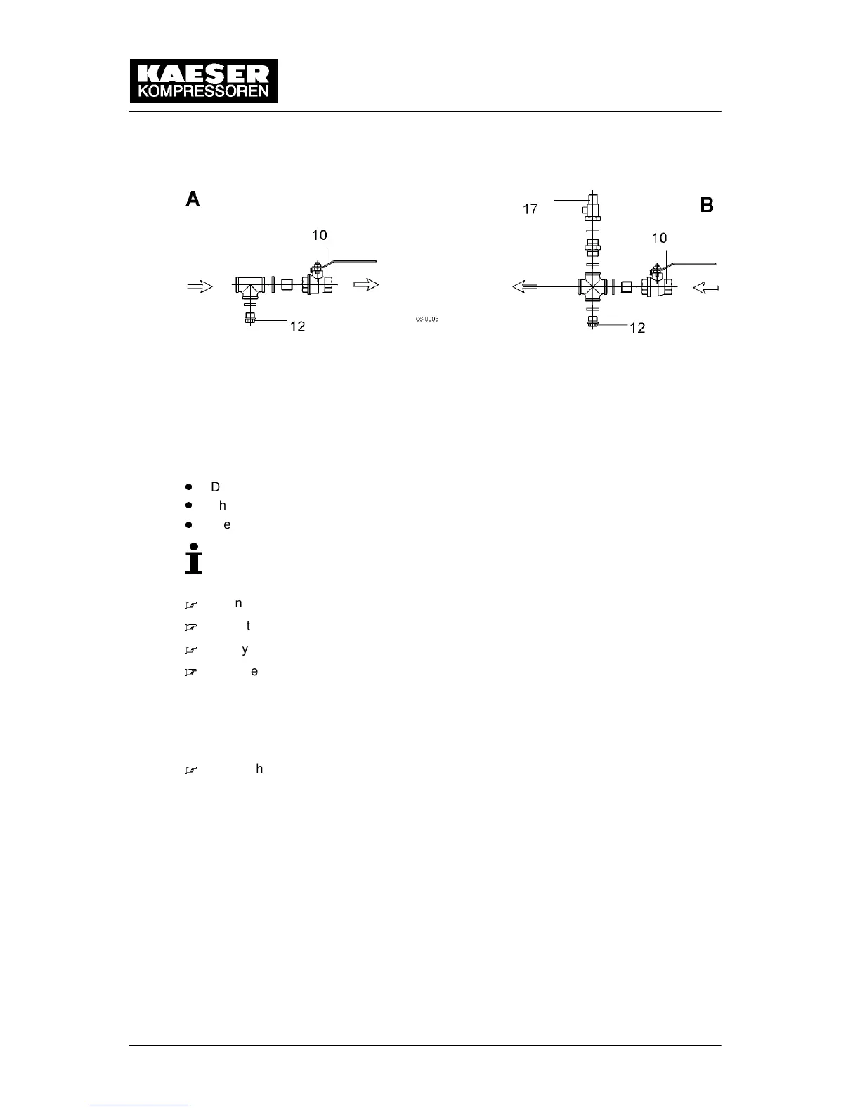
Fig. 14 Heat recovery
A Outlet 10 Shut---off valve
B Inlet 12 Connection port with stopper
17 Pressure relief valve
The user is to provide the following fittings:
Dirt trap with max. 0.1 mm strainer mesh.
Shut---off valves (10) and connection ports (12) for maintenance and venting.
Pressure relief valve (17) on the inlet (B) prevents build---up of excessive pressure.
Blowoff pressure and capacity are related to the user’s installation design.
Keep to the heat exchanger technical specification.
Connect the water lines to the fittings.
Open the shut---off valve on the outlet (A).
Slowly open the inlet (B) shut---off tap to gradually fill the heat exchanger with water.
Vent the lines.
6.5.3.2 External heat recovery system (option W1)
The dimensional drawing in chapter 13.1.3 gives the flow direction, size and position of the
connection ports.
Follow the manufacturer’s instructions on connecting the external heat exchanger.

 Loading...