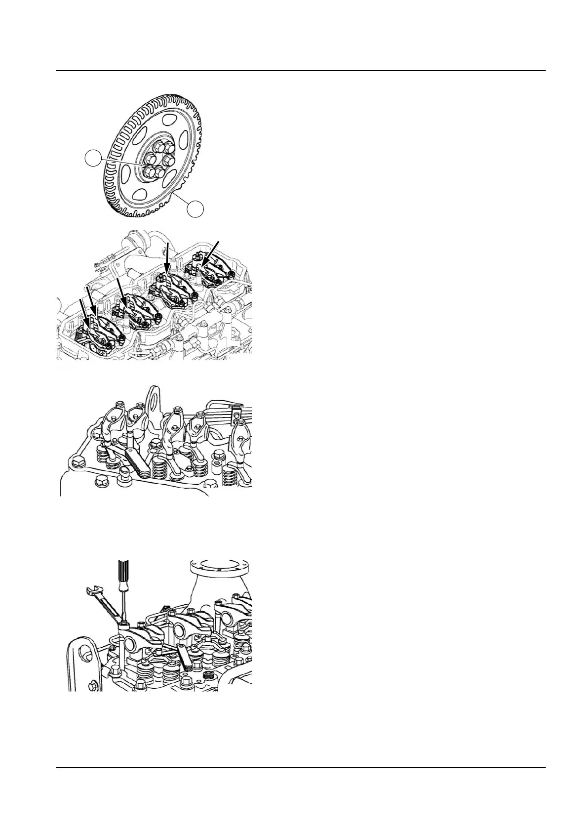
3 If no TDC mark is present on either the vibration damper or
the crankshaft speed indicator ring, align the large gap in the
crankshaft speed indicator ring to the 5 o'clock position (B).
The dowel pin will be visible in the 9 o'clock position (A).
Check that both number 1 cylinder rocker levers are loose. If
they are not loose, rotate the crankshaft 360 degrees and
check again.
4 With the engine in this position, lash can be checked on the
following rocker arms:
(E = exhaust, I = intake)
Four-cylinder 1I, 1E, 2I and 3E
Six-cylinder 1I, 1E, 2I, 3E, 4I and 5E.
Lash Check Limits
mm in
Intake 0.152 MIN 0.006
0.381 MAX 0.015
Exhaust 0.381 MIN 0.015
0.762 MAX 0.030
NOTE
Examing the overhead setting is usually performed as part of a trou‐
bleshooting procedure, and resetting is not required during examina‐
tion, as long as the lash measurements are within the specifications
shown above.
5 Measure the valve lash (overhead set) by inserting a feeler
gauge between the crosshead and the rocker lever socket. If
the measurement is out of specification, loosen the locknut
and adjust the lash to nominal specifications.
NOTE
The clearance is correct when some resistance is “felt” when the
feeler gauge is slipped between the crosshead and the rocker lever
socket.
1 Engine – 1.5 Mechanical components of the engine 15
TL2 Maintenance Manual
591 003 Default