13Kamstrup A/S • 5512887_B2_GB_09.2015
ULTRAFLOW® 54 · DN150-300
2.2.5 Chnge of supply unit
The supply unit of ULTRAFLOW® 54 cn be chnged from mins supply to bttery or vis vers s
the needs of the supply compny chnge. Thus, it cn be n dvntge to chnge mins supplied
meters to bttery meters in buildings under construction where the mins supply cn be unstble
or periodiclly missing.
Plese note tht the supply type of some ULTRAFLOW® sensors ppers from the lbel. If the
originl supply type is chnged, it will no longer be in ccordnce with the lbel.
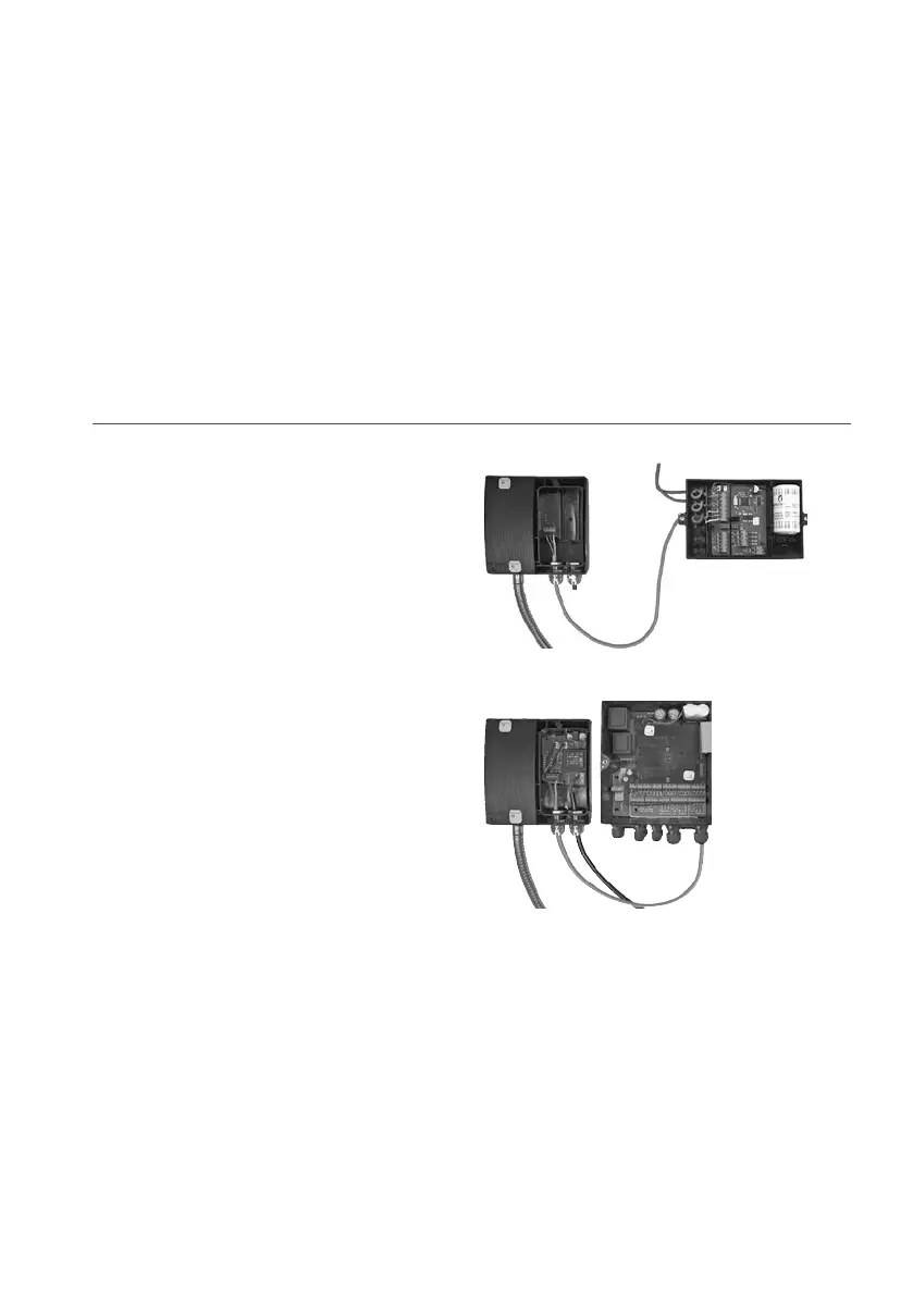
3 Exmple of connection of ULTRAFLOW® 54 to MULTICAL®
ULTRAFLOW® 54 with glvniclly coupled
output module (Y=1), powered by MULTICAL®.
Note: Instlled plug in the unused rightmost
connector of the electronics box.
Figure 12
ULTRAFLOW® 54 with glvniclly seprted
output module (Y=2) nd 230 VAC supply of its
own.
Figure 13

 Loading...


