4 Kamstrup A/S • 5512887_B2_GB_09.2015
ULTRAFLOW® 54 · DN150-300
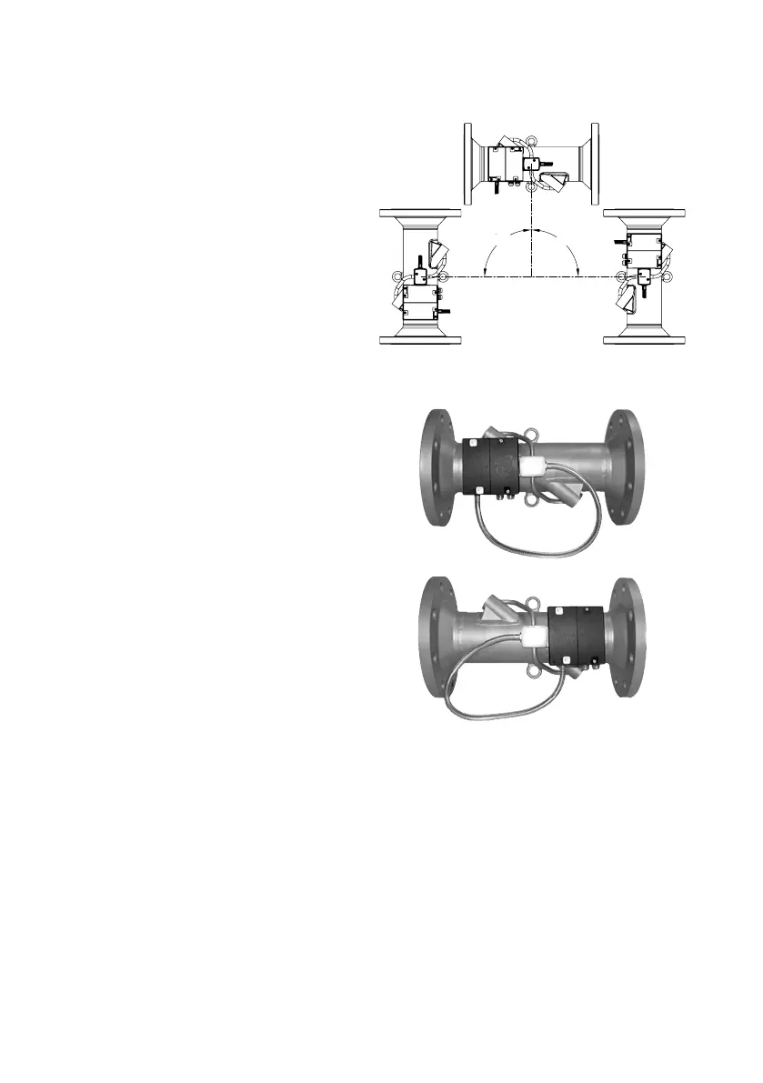
1.1 Instlltion ngle of ULTRAFLOW® 54
ULTRAFLOW® 54 cn be instlled horizontlly,
verticlly, or t n ngle.
ULTRAFLOW® 54 is normlly instlled
horizontlly, the lifting rings being verticlly
oriented. The ultr-sound pths in the flow
sensor tube will thus be verticl, which
is optiml in connection with possible
strtifiction of the medium.
90° 90°
Figure 1
1.1.1 Mounting ULTRAFLOW® 54 in lifting ring
ULTRAFLOW® 54 cn be mounted hnging
from one of the two lifting rings depending on
required flow direction. The enclosed distnce
piece cn be used to secure optiml position
of the electronics box (see prgrph 1.2
”Mounting of ULTRAFLOW® 54 electronics box”,
pge 5)
Figure 2
Figure 3

 Loading...


