7Kamstrup A/S • 5512887_B2_GB_09.2015
ULTRAFLOW® 54 · DN150-300
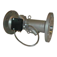
1.2.1 Orienttion of flow sensor electronics box
Mounting the electronics box, the cble connections must lwys be horizontlly or downwrds
oriented in order to void the risk of wter nd condenstion being led into the electronics box vi
the cbles.
This is especilly importnt in humid environments, when ULTRAFLOW® 54 is used s cooling
sensor, or if the medium temperture cn become more thn 5 °C lower thn the mbient
temperture (T
med
< T
mb
- 5 °C).
Furthermore, the steel tube nd wires must in generl hng freely downwrds fter the cble
connections to form drip nose for dringe of wter nd condenstion.
Mx 90°Mx 90°
Figure 8
 Loading...
