5Kamstrup A/S • 5512887_B2_GB_09.2015
ULTRAFLOW® 54 · DN150-300
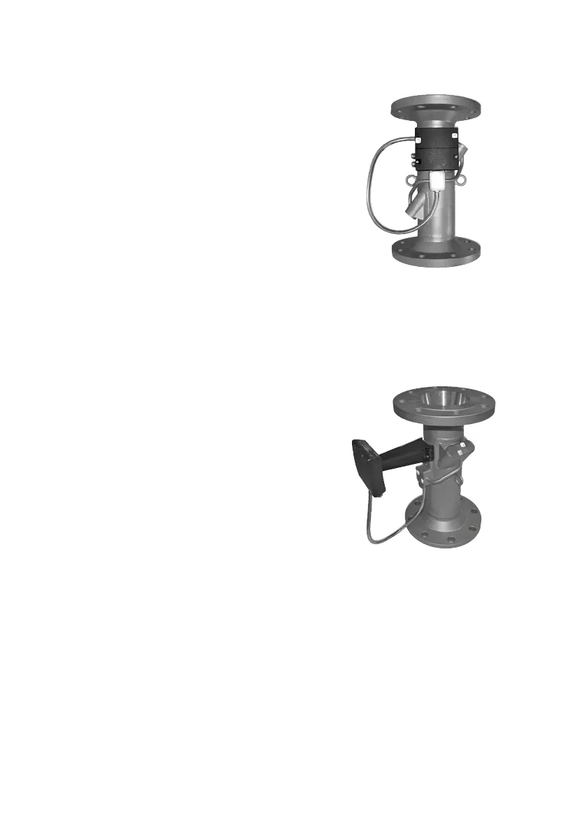
1.2 Mounting of ULTRAFLOW® 54 electronics box
At medium temperture below 90 °C
(T
med
< 90 °C) nd t medium temperture less
thn 5 °C below mbient temperture (T
med
>
T
mb
- 5 °C) the electronics box cn be mounted
directly on the flow sensor housing vi the
fctory mounted fitting.
If the flow sensor is verticlly mounted the
cble connections of the electronics box will
be horizontlly oriented. This is permitted. If
the cble connections should preferbly point
downwrds, the electronics box cn be mounted
vi the enclosed distnce piece, which moves
the box pprox. 170 mm wy from the flow
sensor housing. Alterntively, shorter distnce
piece, which only moves the box pprox. 45
mm wy from the flow sensor housing, cn be
used. The short distnce piece must be ordered
seprtely (6561-332).
Figure 4
At medium temperture bove 90 °C
(T
med
> 90 °C) the temperture is too high for the
electronics box to be mounted directly on the
flow sensor housing.
Therefore, the electronics box must be mount-ed
vi the enclosed distnce piece. The
cble connections must lwys point down-
wrds (see prgrph 1.2.1 ”Orienttion of flow
sensor electronics box”, pge 7).
Alterntively, the electronics box cn be wll
mounted s long s the distnce to flow sensor
housing nd pipe instlltion is minimum
170 mm.
Figure 5

 Loading...


