6 Kamstrup A/S • 5512887_B2_GB_09.2015
ULTRAFLOW® 54 · DN150-300
It cn lso be n dvntge to use the enclosed
distnce piece if the flow sensor housing is
insulted nd the electronics box must be
removed from the insultion.
If the required position of the electronics box
differs from stndrd position, the distnce
piece cn be mounted with the enclosed collr
bnd round the flow sensor housing. However,
plese note tht the cble connections must
lwys point downwrds (see prgrph 1.2.1
”Orienttion of flow sensor electronics box”, pge
7).
Figure 6
At medium temperture more thn 5 °C below mbient temperture (T
med
< T
mb
- 5 °C) (typiclly
in cooling instlltions) it is importnt to tke ction to void condenstion in the electronics box.
Therefore, the electronics box must be mounted vi the enclosed distnce piece. The cble
connections must lwys point downwrds (see prgrph 1.2.1 ”Orienttion of flow sensor
electronics box”, pge 7).
Alterntively, the electronics box cn be wll mounted s long s the distnce to flow sensor
housing nd pipe instlltion is minimum 170 mm.
Furthermore, when mounting the electronics box plese mke sure tht the cble connections on
the box re t higher level thn the cble connection on the flow sensor housing.
By verticl mounting of ULTRAFLOW® 54 in riser this cn be secured by mounting the distnce
piece by mens of the collr bnd s shown in Figure 6.
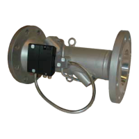
If ULTRAFLOW® 54 is mounted horizontlly the electronics box cn be mounted on the distnce
piece by mens of the collr bnd. The distnce piece cn then be turned upwrds until the cble
connections on the electronics box re in higher position thn the cble connection on the flow
sensor housing. See Figure 7.
Alterntively, the electronics box cn be wll mounted t suitble distnce to the instlltion
(minimum 170 mm).
Figure 7
 Loading...
