3Kamstrup A/S • 5512887_B2_GB_09.2015
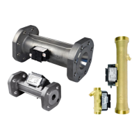
ULTRAFLOW® 54 · DN150-300
1 Instlltion
Prior to instlltion of the flow sensor, the system should be flushed.
Correct flow sensor position (inlet or outlet) ppers from the front lbel of MULTICAL®. The flow
direction is indicted by n rrow on the side of the flow sensor.
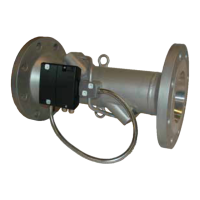
Note: ULTRAFLOW® 54 my be lifted in the lifting rings only.
Pressure stge ULTRAFLOW® 54
PN16/PN25. See mrking on lbel.
Temperture of medium, ULTRAFLOW® 54
2…150 °C/2…130 °C/2…50 °C. See mrking on lbel.
Mechnicl environment
M1 nd M2 (fixed instlltion with minimum vibrtion nd fixed instlltion with considerble or
high vibrtion level respectively). See mrking on lbel.
Electromgnetic environment
E1 nd E2 (housing/light industry nd industry respectively). See mrking on lbel.
The meter’s signl cbles must be drwn t min. 25 cm distnce to other instlltions.
Climtic environment
Must be instlled in environments with non-condensing humidity s well s in closed loctions
(indoors).
The mbient temperture must be within 5…55 °C.
Mintennce nd repir
The flow sensor is verified seprtely nd cn, therefore, be seprted from the clcultor. It is
permitted to replce the supply nd chnge the supply type. For bttery supply lithium bttery
with connector from Kmstrup A/S must be used. Lithium btteries must be correctly hndled
nd disposed of (see Kmstrup document 5510-408, ”Lithium btteries - Hndling nd disposl”).
Other repirs require subsequent reverifiction in n ccredited lbortory.
If ULTRAFLOW® 54 is connected vi glvniclly coupled output module, the flow sensor my be
connected to Kmstrup MULTICAL® clcultor only.
If other clcultor types re connected, ULTRAFLOW® 54 must be fitted with glvniclly
seprted output module nd power supply of its own.
Note: Mke sure tht meter fctors of flow sensor nd clcultor re identicl.
The steel tube between flow sensor housing nd electronics box must not be disssembled.
At medium tempertures bove 90 °C (T
med
> 90 °C) or medium temperture more thn 5 °C below
mbient temperture (T
med
< T
mb
- 5 °C) the flow sensor’s electronics box must be mounted vi the
enclosed distnce piece. Alterntively, the electronics box cn be wll mounted t distnce of
minimum 170 mm from the sensor.
In order to prevent cvittion the bck pressure (the pressure t the flow sensor outlet) t
ULTRAFLOW® 54 must be min. 1.5 br t q
p
nd min. 2.5 br t q
s
. This pplies to tempertures up
to pprox. 80 °C.
When the instlltion hs been completed, wter flow cn be turned on. Vlves on the inlet side
must be opened first.
 Loading...
