8 Kamstrup A/S • 5512887_B2_GB_09.2015
ULTRAFLOW® 54 · DN150-300
1.3 Stright inlet
ULTRAFLOW® 54 requires neither stright inlet nor outlet in order to fulfil the Mesuring
Instruments Directive (MID) 2004/22/ EC nd EN 1434:2007. Only in cse of hevy flow
disturbnces before the meter will stright inlet section be necessry. We recommend following
the guidelines in CEN CR 13582.
Optiml position cn be obtined by tking the below-mentioned instlltion methods into
considertion:
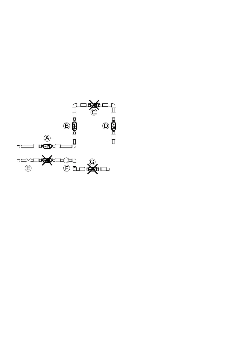
Figure 9
A Recommended flow sensor position.
B Recommended flow sensor position.
C Uncceptble position due to risk of ir build-
up.
D Acceptble in closed systems. Uncceptble
position in open systems due to risk of ir
build-up.
E A flow sensor should not be plced
immeditely fter vlve, except from closing
vlves (bll vlve type), which must be
completely open when not used for closing.
F A flow sensor should not be plced t the
suction side of pump.
G A flow sensor should not be plced fter
double bend in two plnes.
For generl informtion concerning instlltion see CEN report CEN CR 13582, Heat meter
installation. Instructions in selection, installation and use of heat meters.
1.4 Operting pressure
In order to prevent cvittion the bck pressure (the pressure t the flow sensor outlet) t
ULTRAFLOW® 54 must be min. 1.5 br t q
p
nd min. 2.5 br t q
s
. This pplies to tempertures up
to pprox. 80 °C.

 Loading...


