11Kamstrup A/S • 5512887_B2_GB_09.2015
ULTRAFLOW® 54 · DN150-300
2.2 Connection of power supply
If ULTRAFLOW® 54 is mounted with glvniclly coupled output module nd connected to
MULTICAL®, the flow sensor is supplied by the clcultor. Therefore, the flow sensor must not be
fitted with supply of its own.
ULTRAFLOW® 54 my be connected to other clcultors vi the glvniclly seprted output
module only, nd the flow sensor must, therefore, be fitted with supply module or bttery.
Supply module nd bttery re connected to the two-pole connector of the output module.
2.2.1 Bttery supply
ULTRAFLOW® 54 is mounted with D-cell lithium bttery with connector. The bttery plug is
connected to the output module.
Optiml bttery lifetime is obtined by keeping the bttery temperture below 30 °C, e.g. by wll
mounting the electronics box.
The voltge of lithium bttery is lmost constnt throughout the lifetime of the bttery (pprox.
3.65 V). Therefore, it is not possible to determine the remining cpcity of the bttery by
mesuring the voltge.
The bttery cnnot nd must not be chrged nd must not be short-circuited.
The bttery supply my only be replced by corresponding lithium bttery with connector from
Kmstrup A/S. Used btteries must be hnded in for pproved destruction, f.inst. t Kmstrup A/S.
(See Kmstrup document 5510-408, ”Lithium btteries - Hndling nd disposl”).
2.2.2 Mins supply modules
The mins supply modules re protection clss II nd re connected to the output module vi
two-pole connector. The modules re powered vi two-wire supply cble (without erth
connection) through the cble connector of the electronics box. Use supply cble with n outer
dimeter of 4.5-10 mm nd ensure correct dismntling s well s correct tightening of cble
connection (see prgrph 2.2.4 “Cble connections”, pge 12).
Mx. permitted fuse: 6 A.
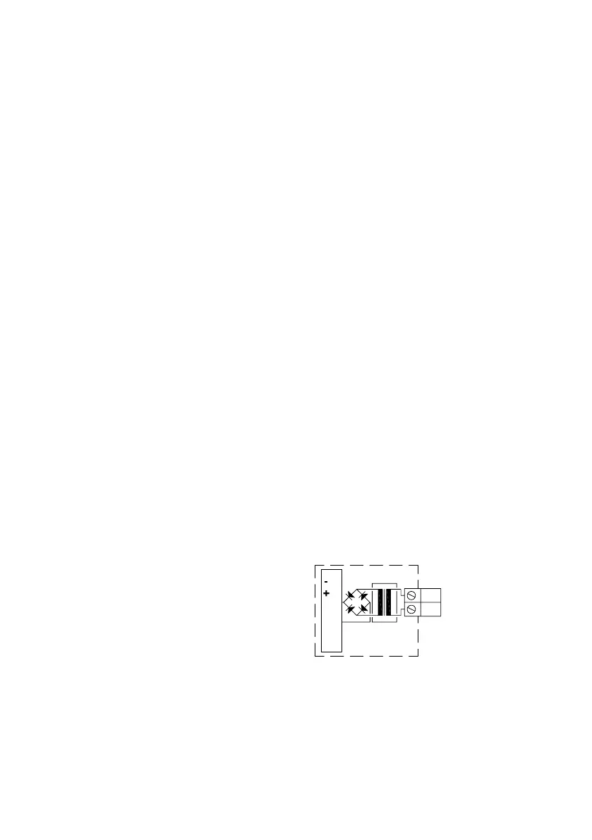
230 VAC
This PCB module is glvniclly seprted from
the mins voltge nd is suitble for direct
230 V mins instlltion. The module includes
double-chmber sfety trnsformer, which
fulfils double-isoltion requirements when the
cover is mounted on the electronics box. Power
consumption is less thn 1 VA or 1 W.
27
28
230 VAC supply
230 VAC
3.6 V
65-000-000-7000
Digrm 5
Ntionl regultions for electric instlltions must be observed. The 230 VAC module cn be
connected/disconnected by the district heting sttion’s personnel, wheres the fixed 230 V
instlltion in the min electricl pnel must be crried out by n uthorized electricin.

 Loading...


