19
Damage to the cable due to exceeding the minimum bending radius!
If the minimum bending radius of the connecting cables is exceeded the cable
strands can break.
Make sure that the cable is not kinked, pinched or excessively bent.
For the power supply of the CEU, the external power supply unit is connected to the 3-pin connector (A2)
(Refer to Para. 4.5.1).
The I/O trigger and signal processing is done through the 13-pin Souriau 8 STA 21035 PN connector (M2)
(Refer to Para. 4.5.2.1).
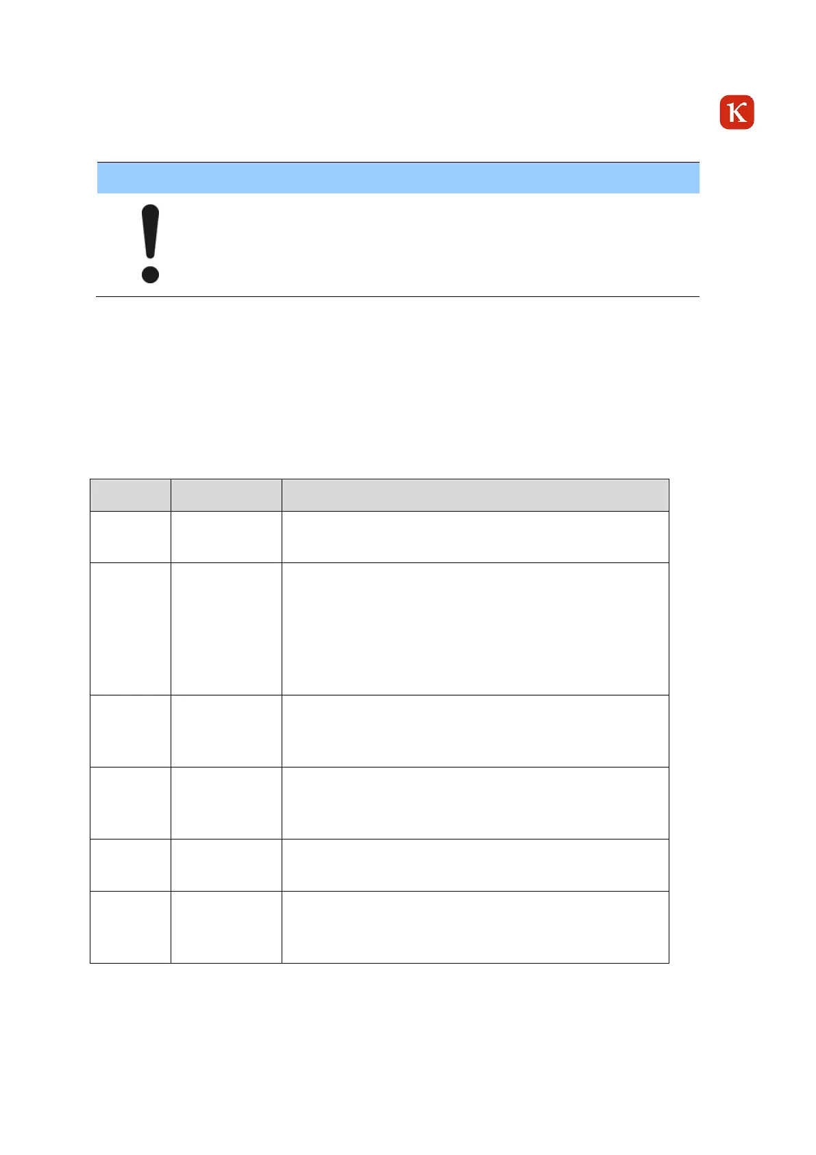
4.3.4.1 LED Status (CEU)
State directly after powering on the device.
After booting entering camera configuration:
Load Camera Parameters from NAND
IP-Configuration
FDP Link Configuration
IPIPE Configuration
PBIT Test
Acquisition started.
Build In Test Loop Running
Image Acquisition (Streaming) running
Acquisition stopped.
Build In Test Loop Running
Image Acquisition (Streaming) stopped
Error detected.
PBIT / CBIT
Image Acquisition may be degraded.
Table 4-1 LED Status CEU