Home
Kappa
Digital Camera
Flight Eye FE320
Page 38
Kappa Flight Eye FE320 - Page 38
45 pages
Manual
Save Page as PDF
To Next Page
To Next Page
To Previous Page
To Previous Page
Loading...
38
Step
Procedure
Figure
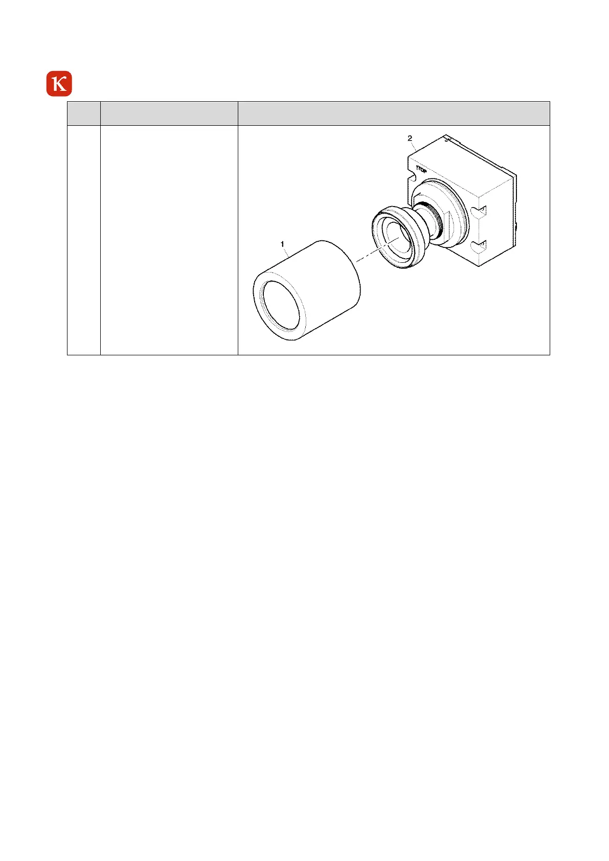
6
Carefully install the tube (1)
to the camera head (2). Turn
the tube (1) clockwise onto
the thread and tighten the
tube (1) with your hands.
Make sure that you do not
touch or damage the optic.
37
39
Table of Contents
Main Page
Default Chapter
4
Table of Contents
4
1 Introduction
7
Intended Use
7
Foreseeable Misuse
7
Warranty
7
Scope of Delivery
8
Scope of Delivery of the Camera Electronic Unit (CEU)
8
Scope of Delivery of the Camera Sensor Unit (CSU)
8
Table 1-1 Scope of Delivery
8
Table 1-2 Scope of Delivery
8
Safety Instructions
9
2 System Requirements
10
Software
10
Hardware
10
3 Quick-Start
11
System Requirements
11
Camera Connections
11
Installation of KCC-X
11
Open KCC-X
11
Figure 3-1 Camera Electronic Unit - Rear View
11
System with Directly Connected Camera (Without DHCP Server)
12
System with Network
12
Network Without DHCP Server
12
Network with DHCP Server
12
Controlling Via KCC-X
12
Figure 3-2 Camera Sensor Unit - Directly Connected to a PC
12
Figure 3-3 Camera Sensor Unit - Network with DHCP Server
12
4 Build-Up and Function
13
General
13
Figure 4-1 Overview Flight Eye FE 320 - Flight Test Camera Kit Modules
14
Figure 4-2 Example Flight Eye FE320 Kit - Direct Connection - no Wire - 370-0399 - 962
15
Family Setups
16
Figure 4-3 Family Setup 1
16
Figure 4-4 Family Setup 2
16
Figure 4-5 Family Setup 3
16
Parts Designation
17
Front of the Camera Sensor Unit (CSU)
17
Rear of the Camera Sensor Unit (CSU)
17
Figure 4-6 Example Camera Sensor Unit (CSU)
17
Figure 4-7 Example Camera Sensor Unit - Rear View
17
Front of the Camera Electronic Unit (CEU)
18
Rear of the Camera Electronic Unit (CEU)
18
Figure 4-8 Camera Electronic Unit - Front View
18
Figure 4-9 Camera Electronic Unit - Rear View
18
Table 4-1 LED Status CEU
19
Dimensions
20
Figure 4-10 Camera Sensor Unit (P/N 370-0413) - Dimensions
20
Figure 4-11 Camera Electronic Unit - Dimensions (P/N 962-0102)
20
Connections
21
Power Supply Connector A2 - CEU
21
Table 4-2 Power Supply Connector A2 - CEU
21
Communication Connector M2 - CEU
22
Table 4-3 A2-Pin Configuration CEU
22
Table 4-4 Communication Connector M2
22
Table 4-5 M2-Pin Configuration CEU
23
Grounding Screw
24
Table 4-6 Grounding Screw
24
Camera Properties
25
Environmental Conditions
25
Sensor Type
25
Spectral Sensitivity
25
Resolution
25
Modes of Operation
25
Identification Data of the Camera
25
General User Setting
25
Test Functions
26
Automatic Gain and Exposure Time
26
Gamma Correction
27
Privacy Mask Feature
27
Exposure Modes
27
Figure 4-12 Privacy Mask Feature
27
Software-Reset
28
Figure 4-13 Chronological Sequence of Exposure and Readout Time in the Exposure Mode "Reset /Restart
28
5 CEU Installation
29
Figure 5-1 CEU Installation - Example
29
6 Initial Operation
30
Precautions
30
Recommended Hardware for the Camera Operation
30
Table 6-1 Recommended Hardware for the Camera Operation
30
Preparation for Operation
31
Turning on the FE320
32
7 Operation
32
Frozen Image Indication
32
Figure 7-1 Camera FE320- Frozen Image Indication
32
8 Troubleshooting
33
9 Maintenance/Cleaning
33
Cleaning
33
Maintenance Work
34
Time Limits
34
Job Set-Up Information
34
Table 9-1 Time Limits
34
Table 9-2 Fixtures, Tools, Test and Support Equipment
34
Table 9-3 Expendables
34
Replacement of the Sealing Ring
35
Table 9-4 Consumables
35
Adjustment of the Lenses
39
Fe320 Csu
39
10 Preservation, Packaging, Transport and Storage
40
Preservation
40
Packaging - CSU/CEU
40
Transport
41
Storage
41
Ambient Conditions
41
Dimensions and Technical Data of the Delivery / Storage-Box
41
11 Disposal
42
12 Technical Data
42
13 Parts List
43
Table 13-1 Parts List CEU
43
Figure 13-1 CEU
44
14 List of Vendors
45
Table 14-1 List of Vendors
45