EN
762.885 Z05 2012 coolcept_fleX, coolcept³_fleX 13
4.8 Grid monitoring
The grid monitoring in the device permanently monitors the grid parameters of the public
grid. If the grid monitoring detects a deviation of the grid parameters from the statutory re-
quirements, the device switches off automatically. When the public grid meets the statutory
requirements again, the device switches on again automatically.
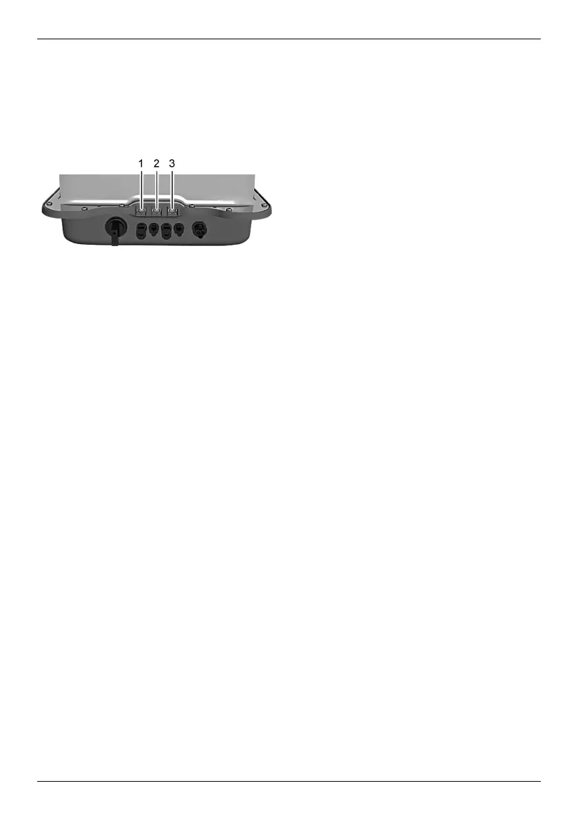
4.9 Data communication
• "LAN" connection (1) (Ethernet for TCP/IP network) for the communication with a central
data server.
• "COM1" connection (2) (RS485 bus) for the communication with external devices, e.g.
with a data logger.
• "COM2" connection (3) (Modbus RTU) for the communication with e.g. an external en-
ergy meter.
4.9.1 "COM1" and "COM2"
The inverter can communicate with other device via the "COM1" and "COM2" connections.
Requirements for the communication:
• Both ends of the data connection are terminated.
• RJ45 standard cables or alternative data connecting cables are used as bus cables.
For further information on connecting further master devices and further inverters refer to
the document "Technical Information" in the download area on the Steca website.
"COM2"
The inverter is able to communicate with energy meters (Modbus RTU) via the "COM2"
connection. To do this, the energy meter must meet the following requirements:
• The energy meter has been programmed in the inverter.
• The energy meter measures the draw from the grid in positive direction (refer to instruc-
tions of the energy meter).