Rev. 1.00
22586_EDEBDA0253-0318-1_EN
20
KBR multicomp F144-3 6DO/6RO
5 Commissioning the system
5.1 General notes on commissioning
The controller is con gured as a compensation system component (see con-
nection diagram) by default. The following settings need to be con gured or
checked:
Target cos phi according to the energy supplier's speci cations.
Primary and secondary current in the main circuit in accordance with the
mounted transformer.
Set the measuring voltage transformer data, if necessary.
If no stage powers have been con gured, the controller will switch to the
Commissioning menu after initialization. Next, stage power programming can
be performed in the settings menu, or using the learning process.
NOTE
You can start the learning process from the "Learning mode activate" submenu
in the Commissioning menu, using the Enter/Input buttons.
If the "Learning mode" window does not open, please check that
Menu on is set for "Learning mode" in the "Extras" menu.
The settings are saved on an EEPROM so that they are not lost in the event of
a power failure.
Switch on a su cient number of inductive consumers (e.g. motors) before
switching the compensation system on. A transformer current of at least 15
mA needs to ow in the secondary circuit for the controller to be activated.
Below this limit, the error message "No transformer current" will be displayed.
Check the transformer connection (is the transformer ratio too high?).
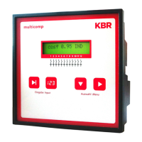
If all connection conditions are OK, the instantaneous power factor cos phi
should be displayed after initialization, e.g. normally, when no capacitors are
connected, cos phi is between 0.6 and 0.9 inductive, (e.g. cos phi 0.80 ind).
If a capacitive value is displayed, or if the "G" symbol is ashing, the phase
allocation of the current and voltage measurement is incorrect.

 Loading...