GB - 10
Control circuit
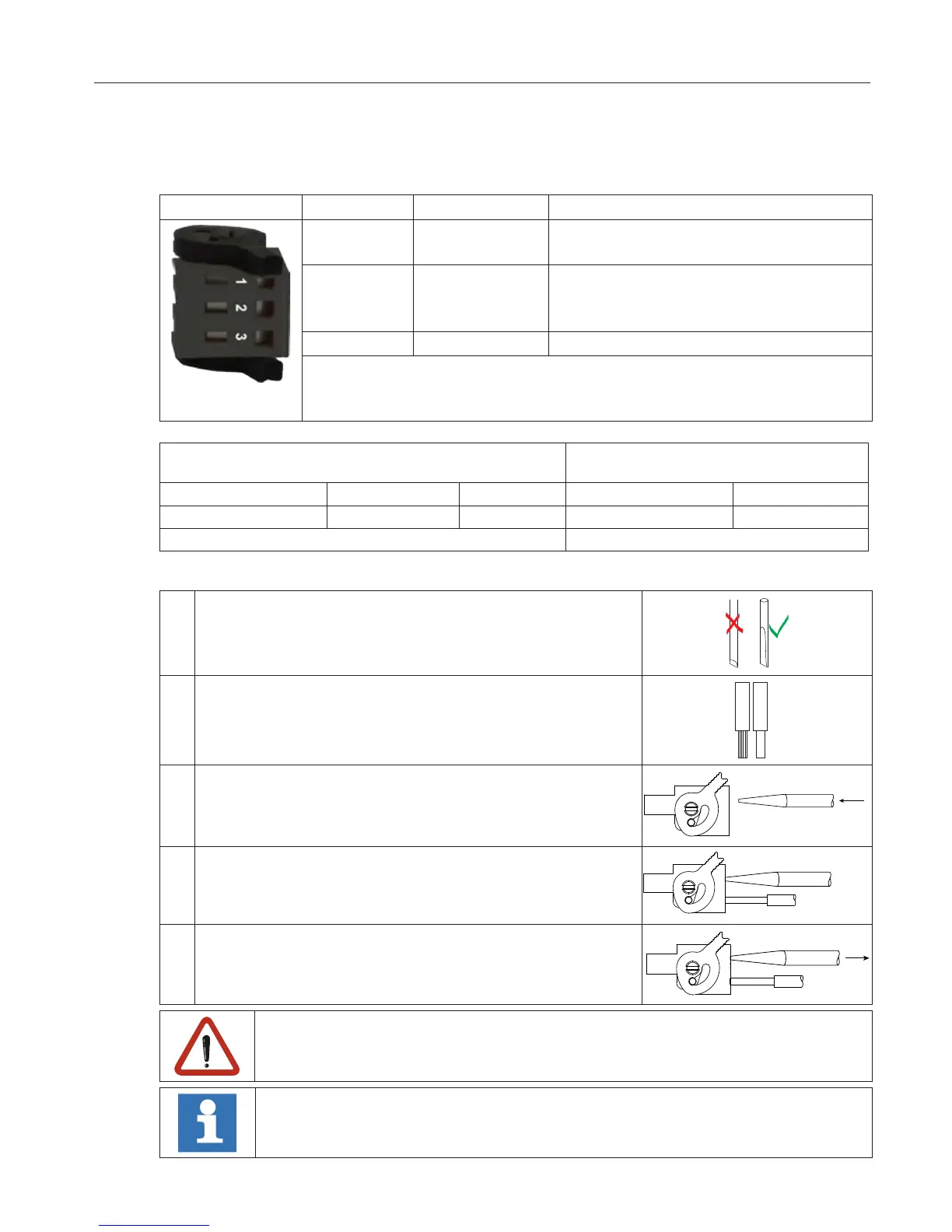
2.1.2 IO-link device interface
X4B PIN Name Function
1 L+ Voltage input
18…30 Vdc / 500 mA
2 C/Q Transmission signal
Input: 18…30 Vdc Ri:10…40 kΩ
Output: 18…30 Vdc I: 220…480 mA
3 L- 0V
Baud rate: 38.4 kBd
Accuracy of the transmission speed: ±0.16 %
Bus and control card supply voltage are not isolated.
Assembly of connecting wires with wire-end ferrules
according to DIN46228/4
Assembly of connecting wires
without wire-end ferrules
Cross-section / AWG
Metal sleeve length
Stripping length
Cross-section / AWG Stripping length
0.2…0.75 mm
2
/ 24…19 6 mm 8 mm 0.2…1.5 mm
2
/ 24…16 10 mm
Connecting wires rigidy and exible
2.1.3 Assembly of the wires
Required tools:
Screw driver SD 0.4 x 2.5 (DIN 5264)
1. Strip cable
Use wire-end ferrules as round, square or hexagon
pressing.
2. Plug screw driver mid into the square slot.
3. Plug cable into the round slot, that no wires can be seen
from the outside.
4. Remove screw driver and check if cables are xed.
A safe clamping can not be guaranteed when using shorter wire-end ferrules.
KEB generally recommends the use of wire-end ferrules in industrial environments.

 Loading...


