GB - 9
Control circuit
2. Control circuit IO-Link
The control provides the following functions:
• IO-link device interface
• Hardware allocation of digital inputs and outputs
• Diagnostic interface (parameter display, scope mode)
• Hardware of the control circuit „safely separated“ according to EN 61800-5-1 (base TN-
C/-S mains)
• LED for inverter state
• optional with safety function STO (separate manual)
• optional f=0 Hz functionality (separate manual)
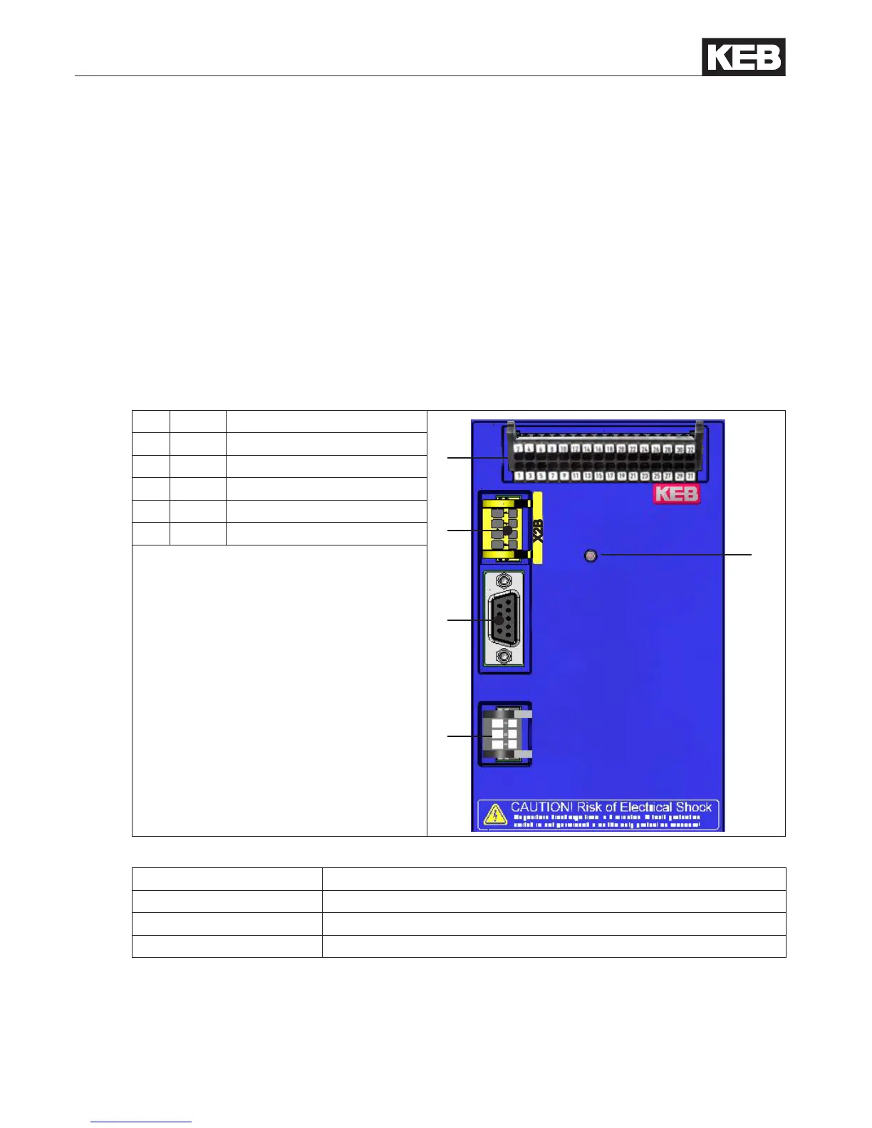
2.1 Overview
No. Name Description
5
4
3
1
2
X2B
X2A
X4A
X4B
LED1
1 X4B IO-link device interface
2 X4A Diagnostic interface
3 X2B Safety function STO
4 X2A Control terminal strip
5 LED1 Inverter status
2.1.1 Inverter status LED1
Pattern Function
off Unit switched off
on Unit ready for operation
ashing Unit in malfunction

 Loading...


