GB - 12
Control circuit
2.1.4.3 Connection of the RS485 interface
The following instructions must be observed in order to prevent interferences at
the RS485 interface:
• use in pairs, twisted and shielded cable
• Ground outer shield at one side (prior at interference-free side)
• Connect terminating resistors (120 Ω) at both ends on pair of wires of the
communication bus
• if available, the internal shielding must be laid at the transmitter to ground
• Lay earth cable between the bus nodes
A biasing can be used if there are still interferences. However, this should be
done only once at the communication bus (preferably at the master).
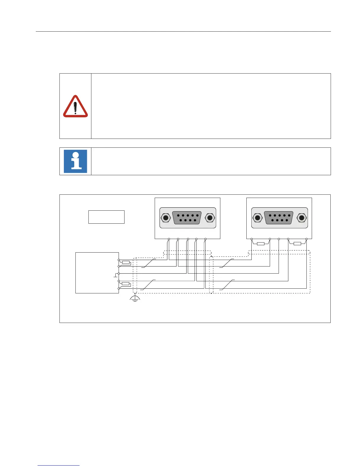
2.1.4.4 Wiring RS485 full duplex
5 4 3 2 1
9 8 7 6
COMBIVERT
5 4 3 2 1
9 8 7 6
COMBIVERT
4 5 8 9
4 5 77 8 9
Master
TxD-A
TxD-B
RxD-A
RxD-B
R R
R
R
R=120Ω
1)
1) The ground connection is used to reduce communication disturbances

 Loading...


