20
Commissioning and conguration
ServoOne User Manual SERCOS II and III
ID no.: 1108.26B.3-00 Date: 04/2020
Commissioning and conguration
5.1.5 Diagnostic LEDs
Hardware variant 1
LED Colour Meaning
H5
H4
H6 H7
H4 Red Distortion LED, interference on the BUS
H5 Green Status of the SERCOS communication
phase (ashing code)
H6 Green Receiver LED, receiving telegrams
H7 Green Transmitter LED, sending telegrams
Hardware variant 2
LED Colour Meaning
H5
H4
H4 Red Distortion LED, interference on the BUS
H5 Green Status of the SERCOS communication
phase (ashing code)
5.1.6 Usage of the distortion indicator
After the drive address has been set, it should be checked whether an adequate
optical signal level is present at each bus user, i.e. whether the receiver is underdriven
or overdriven. The optical level is checked using the Distortion LED on the front of the
ServoOne (LED H4). Normally the Distortion LED is off. To check the optical level, all
drives in the ring are checked in the signal ow direction, starting from the transmitter
output on the master (see gure in sub-section "Connection for the bre optic cable").
The distortion indicators are to be checked in the "direction of the light", i.e. the rst
drive in the ring is to be checked rst. If its distortion indicator is off, check the next
drive. This procedure is continued to the last drive and then undertaken on the master
(controller).
Note:
The distortion indicator must not illuminate or glow.
5.2 SERCOS III
5.2.1 Conguring basic settings
Setting the motion prole parameters
The basic drive settings must be congured as per the reference documents. Then the
following setting must be made with the aid of DriveManager so that it is possible to
change to operation via Sercos.
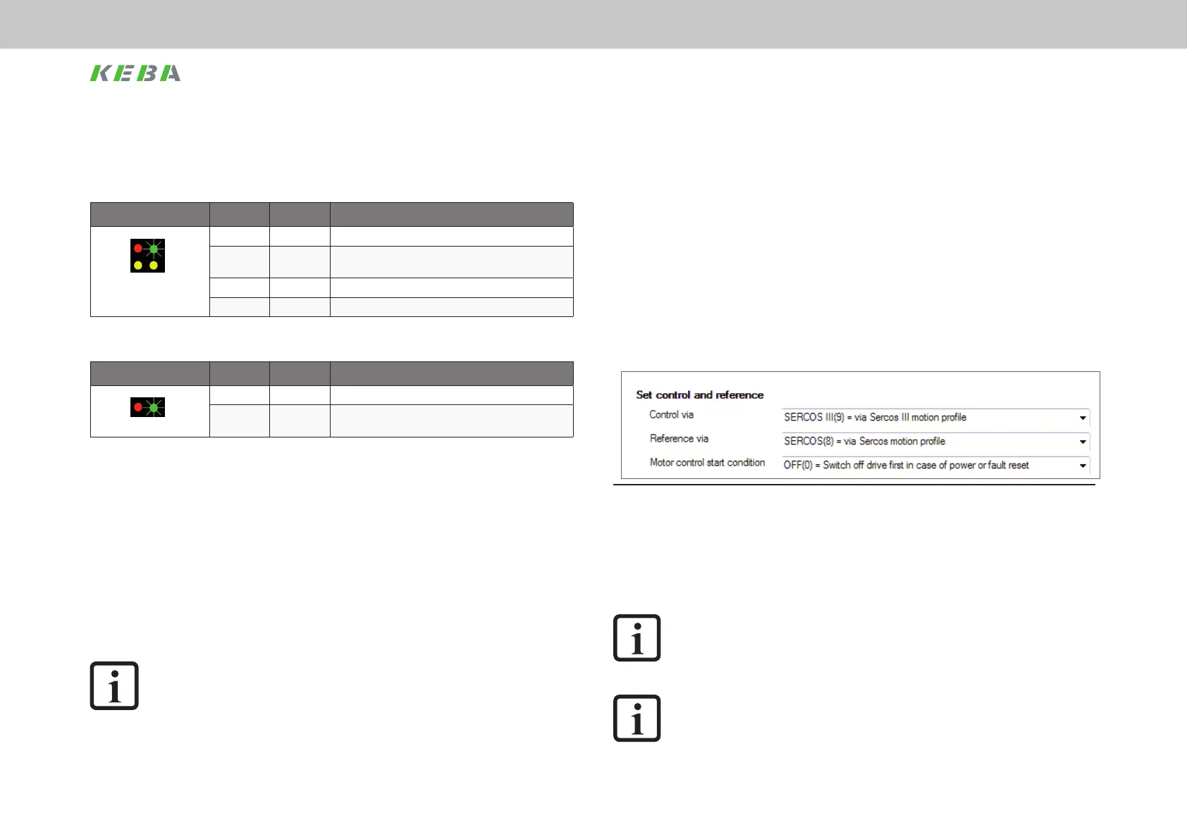
So that the drive can be controlled and moved via SERCOS III, the two parameters
control location selector P-159 MPRO_CTRL_SEL and reference value selector P-165
MPRO_REF_SEL must be set as per the gure below.
Figure 5.2 Basic settings, P-0159 and P-0165 with SERCOS III
Prerequisites:
y The drive is wired as per the operation manual and initial commissioning has
been undertaken.
y If electrical power is to be applied to the motor, the hardware enable (ENPO)
and the "STO (Safe Torque Off)" must also be connected correctly.
NOTE:
You will nd more detailed information on the optimisation of the control
function and control circuits in the application manual for the device.
NOTE:
For information on the topic of "Scaling", please read chapter 6.