39
Data transfer
ServoOne User Manual SERCOS II and III
ID no.: 1108.26B.3-00 Date: 04/2020
Data transfer
Bit no. Description
10 – 8 Actual operation mode
x 000: Main operation mode (denition in S-0-0032.0.0)
x 001: Secondary operation mode 1 (denition in S-0-0033.0.0)
x 010: Secondary operation mode 2 (denition in S-0-0034.0.0)
x 011: Secondary operation mode 3 (denition in S-0-0035.0.0)
x 100: Secondary operation mode 4 (not supported)
x 101: Secondary operation mode 5 (not supported)
x 110: Secondary operation mode 6 (not supported)
x 111: Secondary operation mode 7 (not supported)
7 – 6 Reserved
5 Status of the position actual value (bit 0 of S-0-0403.0.0)
4 Drive stop:
x 0: Drive stop not active
x 1: Drive stop active
3 Reference value application status
x 0: The drive ignores the reference values from the controller (e.g. during move-
ments under drive control (homing run, ..) or delays congured in the parameters).
x 1: The drive follows the reference values from the controller
2 – 0 Reserved
Table 7.3 Drive status word S-0-0135
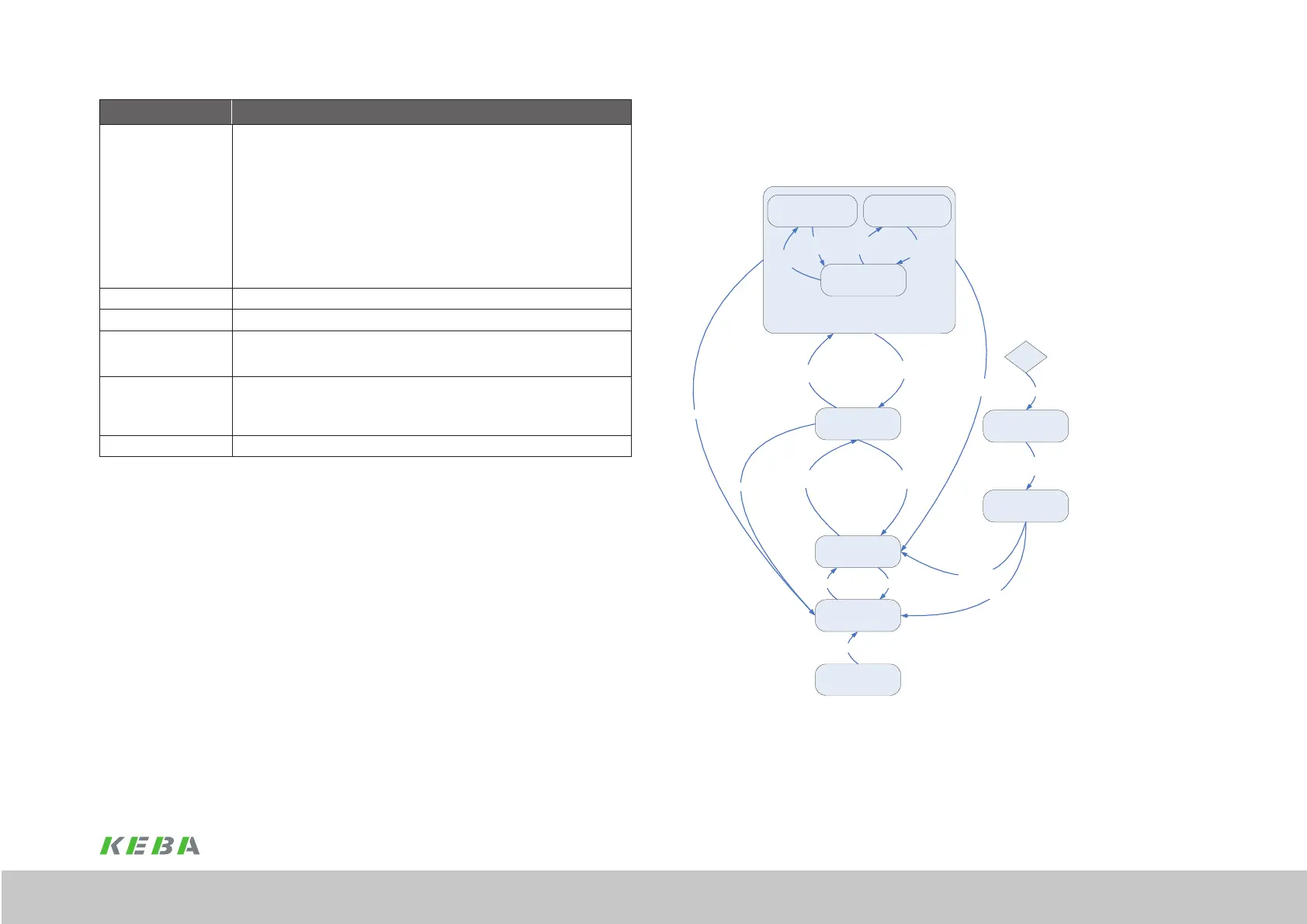
7.3.5 Drive state machine
The system states and the possible state transitions are shown in the gure below and
described in the table below.
Figure 7.2
0 Start
1 UZK OK
2 enable Voltage
(Bit14 =1 & ENPO=1)
5 Disable Voltage
(Bit14=0 | ENPO=0)
3 Enable operation
(Bit 15=1 & Phase 4)
4 disable operation
(Bit 15=0)
5 Disable Voltage
(Bit14=0 | ENPO=0)
9 Fault Reset
6 (UZK off)
8 Fault Reaction
completed
6 (UZK off)
(UZK off)
6 (UZK off)
7 Fault
“Drive stop”
System state 5b
“Command execution”
System state 5c
“Operation mode active”
System state 5a
“Ready to switch on”
System state 3
“Fault reaction active”
System state 7
“Error”
System state 8
“Start inhibit”
System state 2
“Not ready to switch on”
System state 1
“System initialisation
in progress”
System state 0
Error
“Control active”
System state 5
Command
Start
Command
End
Stop
(Bit 13=0)
Start
(Bit 13=1)
General system state machine (control via SERCOS)