Performance Verification
1-15
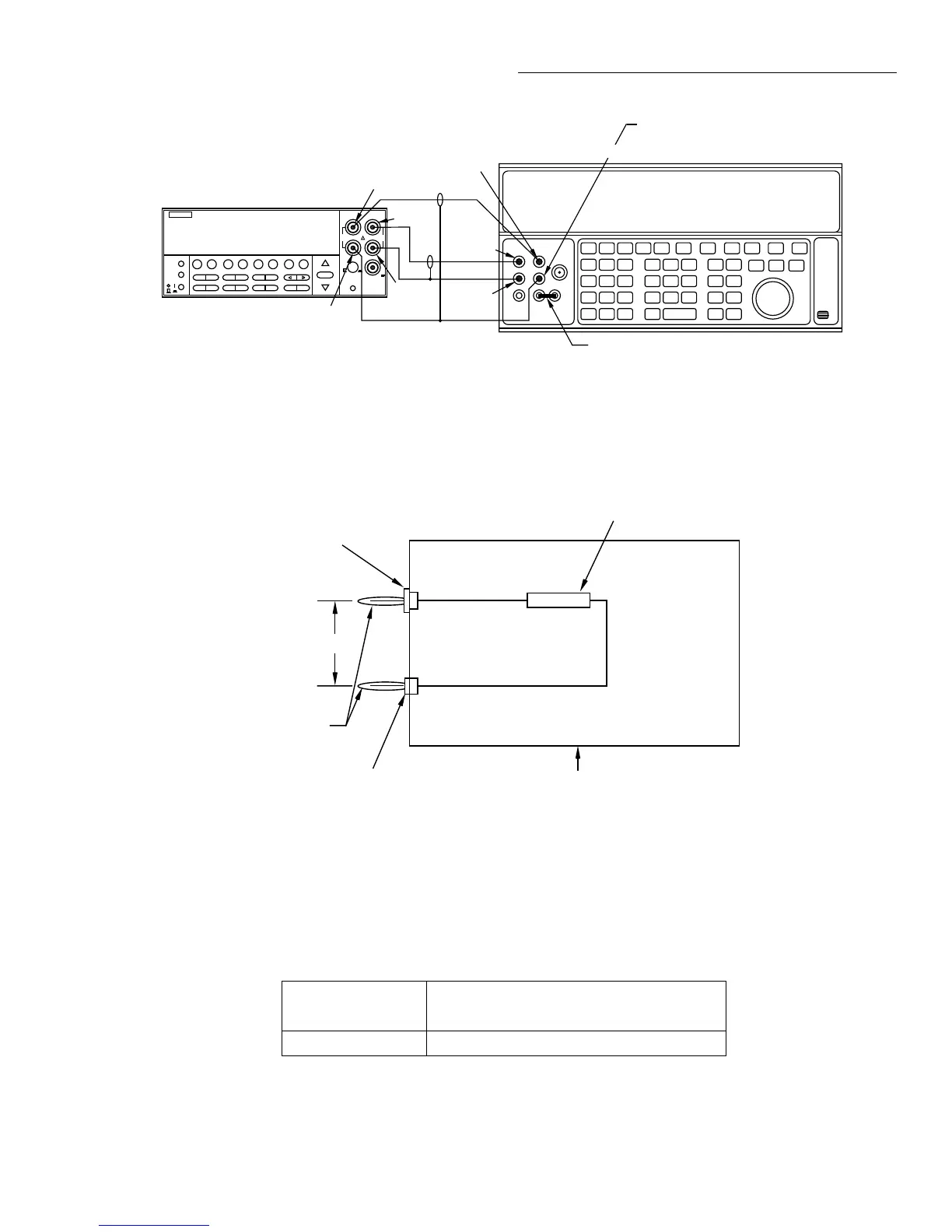
Figure 1-7
Connections for resistance verification (2M¾ - 200M¾ ranges)
NEXT
DISPLAY
PREV
POWER
DCV ACV DCI ACI Ω2 Ω4
FREQ TEMP
REL TRIG STORE RECALL
INFO LOCAL CHAN SCAN CONFIG MENU EXIT ENTER
RANGE
AUTO
FILTER MATH
RANGE
2001 MULTIMETER
SENSE
Ω 4 WIRE
HI
INPUT
LO
INPUTS
CAL
500V
PEAK
F
R
FRONT/REAR
2A 250V
AMPS
350V
PEAK
1100V
PEAK
190.0000 kΩ
Model 2001
Input HI
Output HI
Input
LO
Output
LO
Note: Use shielded cables to minimize noise.
Enable calibrator external sense mode.
Use internal Guard (EX GRD LED is off).
Sense HI
Sense LO
Sense HI
Sense LO
Ground link installed.
5700A Calibrator (Output 4-wire Resistance)
Figure 1-8
1G¾ resistor test box construction
Insulated
Plug
Metal
Test Box
0.75"
HI
LO
Banana
Plugs
Non-insulated Plug
1GΩ Resistor (Keithley
part # R-289-1G)
Note: Resistor must be accurately characterized
before use (see text).
Table 1-9
Limits for resistance verification (1G¾ range)
Characterized
resistor (R) Reading limit (1 year, 18° to 28°C)*
____________ G¾ _________G¾ to _________G¾
*1 Year limits = R ± (0.04R + 100,000)
Where R = characterized value of 1G¾ resistor.

 Loading...


