Performance Verification
1-14
2M¾ – 200M¾ range verification
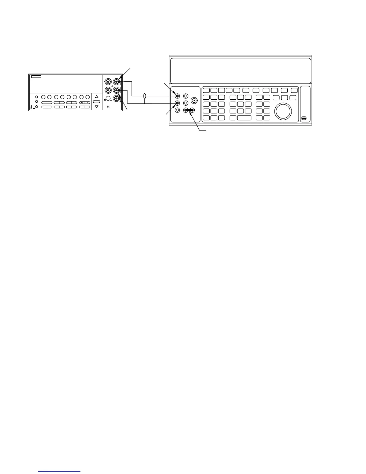
1. Connect the DC calibrator and Model 2001 using the 2-
wire connections shown in Figure 1-7.
2. Set the calibrator to the 2-wire mode (external sense
off).
3. Set operating modes as follows:
A. From normal display, press CONFIG then ¾2.
B. Select FILTER, then press ENTER.
C. Select AVERAGING, then press ENTER.
D. Using the cursor and range keys, set the averaging
parameter to 10 readings, then press ENTER.
E. Press EXIT to return to normal display.
F. If the FILT annunciator is off, press FILTER to en-
able the filter.
4. Select the Model 2001 ¾2 function, and change to the
2M¾ range.
5. Set the calibrator to output 1.90000M¾, and allow the
reading to settle.
6. Verify that the reading is within the limits for the 2M¾
range stated in Table 1-8. (NOTE: Recalculate limits if
actual calibrator resistance differs from value shown.)
7. Repeat steps 4 through 6 for the 20M¾ (output
19.0000M¾) and 200M¾ (output 100.000M¾) ranges.
1G¾ range verification
1. Mount the 1G¾ resistor and the banana plugs to the test
box, as shown in Figure 1-8. Be sure to mount the ba-
nana plugs with the correct spacing. The resistor should
be completely enclosed in and shielded by the metal test
box. The resistor LO lead should be electrically con-
nected to the test box to provide adequate shielding.
Figure 1-6
Connections for resistance verification (20¾-200k¾ ranges)
NEXT
DISPLAY
PREV
POWER
DCV ACV DCI ACI Ω2 Ω4
FREQ TEMP
REL TRIG STORE RECALL
INFO LOCAL CHAN SCAN CONFIG MENU EXIT ENTER
RANGE
AUTO
FILTER MATH
RANGE
2001 MULTIMETER
SENSE
Ω 4 WIRE
HI
INPUT
LO
INPUTS
CAL
500V
PEAK
F
R
FRONT/REAR
2A 250V
AMPS
350V
PEAK
1100V
PEAK
+1. 900000 kΩ
Input HI
Output HI
Input
LO
Output
LO
Model 2001
5700A Calibrator (Output 2-Wire Resistance)
Note: Use shielded cable to minimize noise.
Disable calibrator external sense mode.
Use internal Guard (EX GRD LED is off).
Ground link installed.
2. Characterize the 1G¾ resistor to within ±10,000ppm or
better using an accurate megohmmeter (see Table 1-1).
Record the characterized value where indicated in Table
1-9. Also, compute the limits based on the value of R us-
ing the formula at the bottom of the table.
NOTE
The value of the 1G¾ resistor should not
exceed 1.05G¾.
3. Set operating modes as follows:
A. From normal display, press CONFIG then ¾2.
B. Select FILTER, then press ENTER.
C. Select AVERAGING, then press ENTER.
D. Using the cursor and range keys, set the averaging
parameter to 10 readings, then press ENTER.
E. Press EXIT to return to normal display.
F. If the FILT annunciator is off, press FILTER to en-
able the filter.
4. Select the 2-wire ohms function (¾2) and the 1G¾
range on the Model 2001.
5. Connect the 1G¾ resistor test box (from steps 1 and 2)
to the INPUT HI and LO terminals of the Model 2001.
Allow the reading to settle.
6. Verify that the Model 2001 reading is within the limits
you calculated and recorded in Table 1-9.

 Loading...


