Calibration
2-16
26. Press ENTER, and note that the instrument displays the
following during 1M¾ calibration:
Performing 1.0 MOhm Calibration
27. At this point, the instrument will display the following
message advising you to disconnect test leads:
OPEN CIRCUIT INPUTS
28. Disconnect all test leads from the INPUT and SENSE
jacks, then press ENTER. During this calibration phase,
the instrument will display the following:
Performing Open-Ckt Calibration
29. After open circuit calibration, the instrument will dis-
play the following message:
AC CALIBRATION PHASE
30. Make sure all test leads are still disconnected from the
Model 2001 INPUT and SENSE jacks.
31. Press ENTER to perform AC calibration, which will
take a while to complete. During AC calibration, the in-
strument will display the following:
Calibrating AC: Please wait
32. After the AC calibration phase is completed, the instru-
ment will display the following:
AC CAL COMPLETE
33. Press ENTER. The instrument will display the follow-
ing to indicate the start of the low-level calibration
phase:
LOW-LEVEL CAL PHASE
NOTE
Use the exact calibration values shown
when performing the following steps.
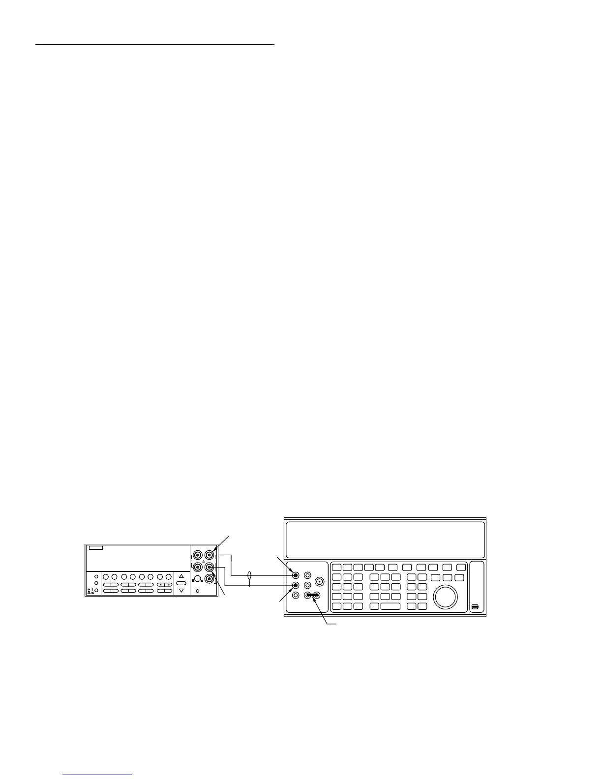
34. Connect the calibrator to the INPUT terminals, as
shown in Figure 2-3.
35. Press ENTER. The instrument will display the follow-
ing:
Connect 20V @ 1kHz
36. Set the calibrator to output 20V AC at a frequency of
1kHz, then press ENTER. The instrument will display
the following:
Low-Level Cal - Step 1 of 15
37. Next, the instrument will prompt for a new calibration
signal:
Connect 20V @ 30kHz
38. Program the calibrator for an output voltage of 20V AC
at 30kHz, then press ENTER. The instrument will dis-
play the following while calibrating this step:
Low-Level Cal - Step 2 of 15
39. The Model 2001 will then display:
Connect 200V @ 1kHz
40. Set the calibrator output to 200V AC at a frequency of
1kHz, then press ENTER. The Model 2001 will display
the following message:
Low-Level Cal - Step 3 of 15
41. When finished with this step, the Model 2001 will dis-
play:
Connect 200V @ 30kHz
42. Set the calibrator output to 200V AC at 30kHz, then
press ENTER. The Model 2001 will display the follow-
ing:
Low-Level Cal - Step 4 of 15
Figure 2-3
Calibration voltage connections
NEXT
DISPLAY
PREV
POWER
DCV ACV DCI ACI Ω2 Ω4
FREQ TEMP
REL TRIG STORE RECALL
INFO LOCAL CHAN SCAN CONFIG MENU EXIT ENTER
RANGE
AUTO
FILTER MATH
RANGE
2001 MULTIMETER
SENSE
Ω 4 WIRE
HI
INPUT
LO
INPUTS
CAL
500V
PEAK
F
R
FRONT/REAR
2A 250V
AMPS
350V
PEAK
1100V
PEAK
Input HI
Output HI
Input
LO
Output
LO
Model 2001
5700A Calibrator
Ground link installed.
Note: Use internal Guard (EX GRD LED is off).
 Loading...


