Calibration
2-17
43. The unit will then prompt for the next calibration signal:
Connect 1.5V @ 1kHz
44. Set the calibrator for 1.5V AC at a frequency of 1kHz,
then press ENTER. The Model 2001 will display the
following:
Low-Level Cal - Step 5 of 15
45. After step 5, the unit will display the following:
Connect 200mV @ 1kHz
46. Program the calibrator to output 200mV at a frequency
of 1kHz, then press ENTER. The Model 2001 will then
display the following:
Low-Level Cal - Step 6 of 15
47. When finished with step 6, the unit will display the fol-
lowing:
Connect 5mV @ 100kHz
48. Set the calibrator to output 5mV at a frequency of
100kHz, then press ENTER. The Model 2001 will then
display the following while calibrating:
Low-Level Cal - Step 7 of 15
49. Following step 7, the instrument will display the follow-
ing message to prompt for the next calibration signal:
Connect 0.5mV @ 1kHz
50. Program the calibrator to output 0.5mV at 1kHz, then
press ENTER. The unit will display the following in-
progress message:
Low-Level Cal - Step 8 of 15
51. Next, the unit will prompt for the next calibration signal:
Connect +2 VDC
52. Set the calibrator to output +2V DC, then press the EN-
TER key. The Model 2001 will advise you that the
present step is in progress:
Low-Level Cal - Step 9 of 15
53. After this step has been completed, the unit will display
the following:
Connect -2 VDC
54. Set the calibrator for an output voltage of -2V DC, then
press ENTER. The Model 2001 will display the follow-
ing message:
Low-Level Cal - Step 10 of 15
55. The Model 2001 will then prompt for the next calibra-
tion signal:
Set calibrator to 0V
56. Program the calibrator to output 0 VDC, then press the
ENTER key. The Model 2001 will display the follow-
ing:
Low-Level Cal - Step 11 of 15
57. After completing step 11, the unit will display the fol-
lowing:
Connect 20mA @ 1kHz
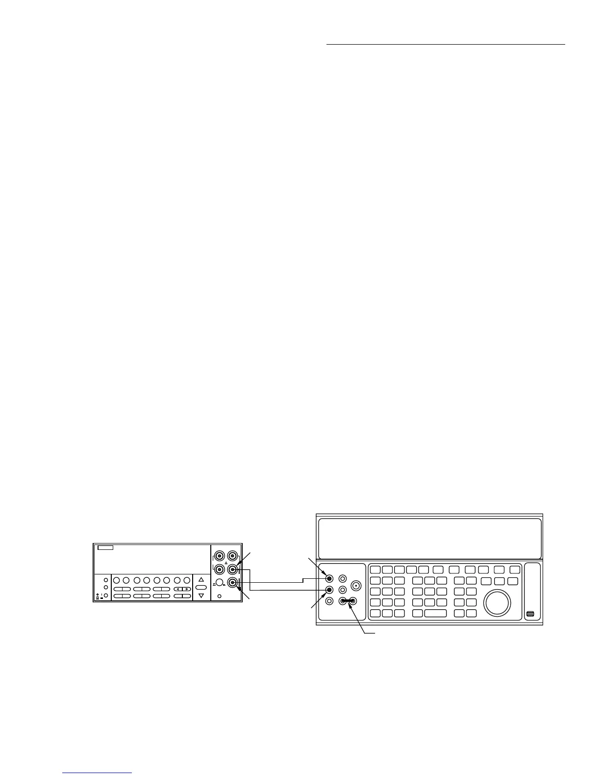
58. Connect the calibrator to the AMPS and INPUT LO
jacks, as shown in Figure 2-4.
59. Set the calibrator output to 20mA AC at a frequency of
1kHz, then press the ENTER key. The Model 2001 will
display the following while calibrating:
Low-Level Cal - Step 12 of 15
60. The unit will then prompt for the next calibration signal:
Connect +0.2ADC
Figure 2-4
Current calibration connections
NEXT
DISPLAY
PREV
POWER
DCV ACV DCI ACI Ω2 Ω4
FREQ TEMP
REL TRIG STORE RECALL
INFO LOCAL CHAN SCAN CONFIG MENU EXIT ENTER
RANGE
AUTO
FILTER MATH
RANGE
2001 MULTIMETER
SENSE
Ω 4 WIRE
HI
INPUT
LO
INPUTS
CAL
500V
PEAK
F
R
FRONT/REAR
2A 250V
AMPS
350V
PEAK
1100V
PEAK
Output HI
Input
LO
Output
LO
Model 2001
5700A Calibrator
Amps
Note: Be sure calibrator is set for normal current output.
Use internal Guard (EX GRD LED is off).
Ground link installed.
 Loading...


