Calibration Programs
B-3
B.6 General program instructions
1. With the power off, connect the Model 2002 and the
calibrator to the IEEE-488 interface of the computer. Be
sure to use shielded IEEE-488 cables for bus
connections.
2. Turn on the computer, the Model 2002, and the calibra-
tor. Allow the Model 2002 to warm up for at least four
hours before performing calibration.
3. Make sure the Model 2002 is set for a primary address
of 16. You can check or change the address as follows:
A. Press MENU, select GPIB, then press ENTER.
B. Select MODE, then press ENTER.
C. Select ADDRESSABLE, and press ENTER.
D. If the address is set correctly, press EXIT as neces-
sary to return to normal display.
E. To change the address, use the cursor keys to set the
address to 16, then press ENTER. Press EXIT as
necessary to return to normal display.
4. Make sure the calibrator primary address is at its factory
default setting of 4.
5. Make sure that the computer IEEE-488 bus driver soft-
ware (CECHP.EXE) is properly initialized.
6. Enter the BASIC or Turbo C editor, and type in the de-
sired program. Check thoroughly for errors, then save
the program using a convenient filename.
7. Compile and/or run the program, and follow the
prompts on the screen to perform calibration.
B.7 Unlocking calibration
In order to unlock comprehensive calibration, briefly press in
on the CAL switch with the power turned on. To unlock low-
level calibration, press in and hold the CAL switch while
turning on the power.
B.8 Comprehensive calibration
Programs B-1 and B-2 will perform comprehensive calibra-
tion almost fully automatically using the Fluke 5700A Cali-
brator. Figure B-1 shows low-thermal short connections,
while Figure B-2 shows calibrator connections.
B.9 Low-level calibration
Programs B-3 and B-4 perform low-level calibration using
the Fluke 5700A calibrator. Refer to Figure B-1 and B-3 for
low-thermal short and calibrator voltage connections. Figure
B-4 shows calibrator current connections. Figure B-5 shows
synthesizer connections necessary to supply the 2V AC 1Hz
signal.
NOTE
Low-level calibration is not normally re-
quired in the field unless the Model 2002
has been repaired.
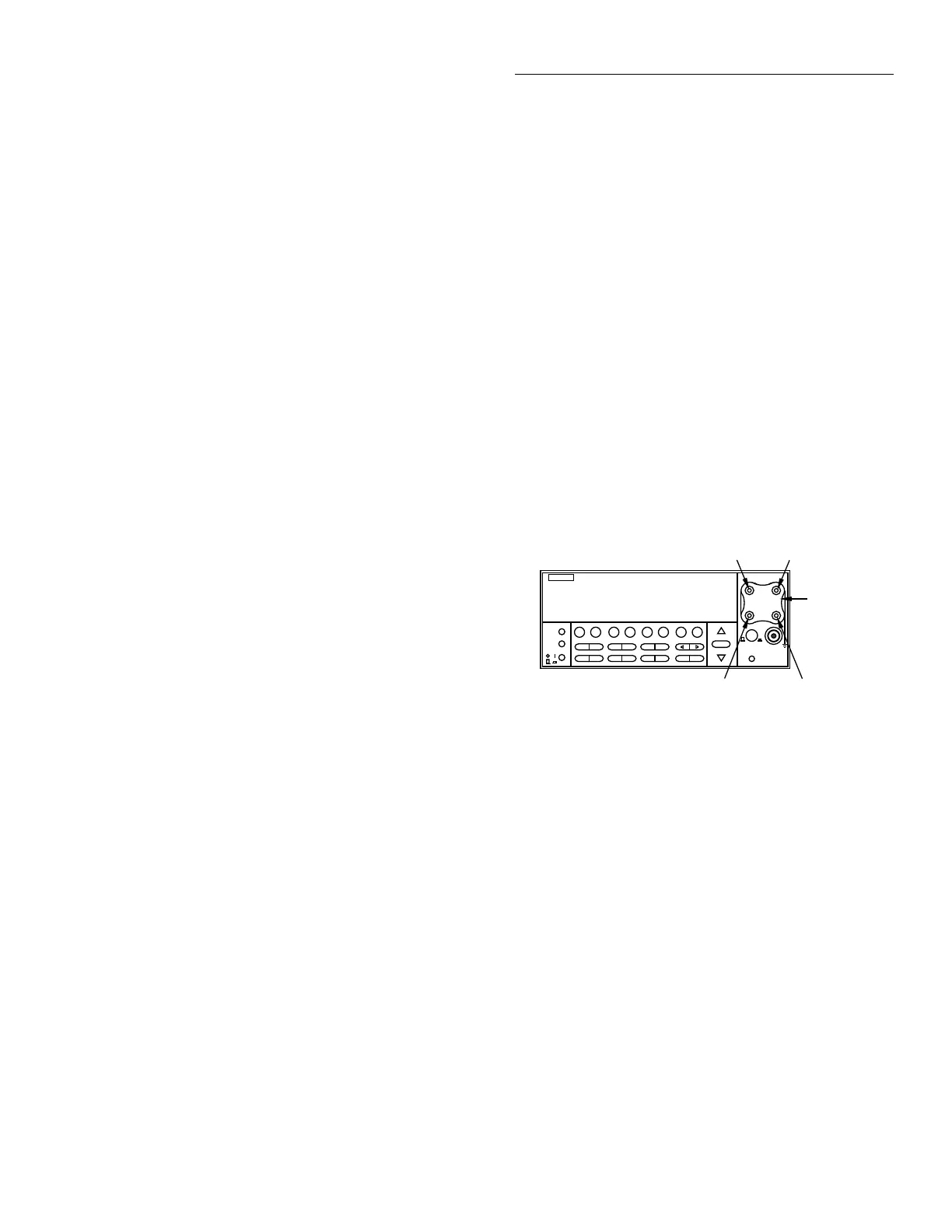
Figure B-1
Low-thermal short connections
2002 MULTIMETER
Model 2002
S+ HI
LOS-
Model 8610
Low-thermal
short
Note: Connect low-thermal short to rear
panel input jacks and select rear
inputs only for low-level calibration
step #11.