1-4 Performance Verification
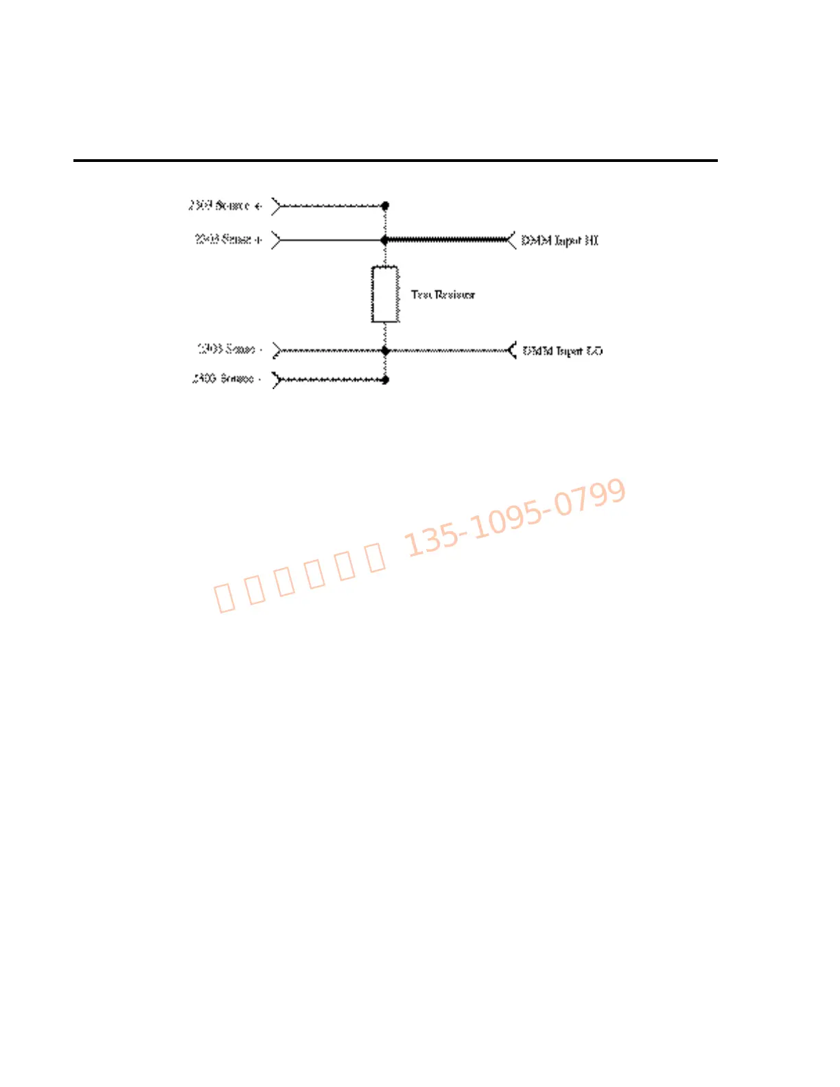
Figure 1-1
Test resistor connections
Resistorconsiderations
The test resistors should be characterized using the lowest possible range and the 4-wire ohms
function of the DMM recommended in Table 1-1 to measure the resistance values. Use the mea-
sured resistance values to calculate the actual currents during the test procedures.
NOTE The temperature coefficient and temperature change of the 1Ω and 30Ω resistors
when passing current at full load must be low enough so that the change in resistance
does not cause incorrect readings as follows:
V
OUT
/∆R <25% of Model 2303 amps specification. (V
OUT
is the Model 2303 output
voltage, and ∆R is the change in resistance caused by heating.)
Verificationlimits
The verification limits stated in this section have been calculated using only the Model 2303
accuracy specifications, and they do not include test equipment uncertainty. If a particular mea-
surement falls outside the allowable range, recalculate new limits based both on Model 2303
specifications and corresponding test equipment specifications.
Examplelimitscalculation
As an example of how verification limits are calculated, assume you are testing the power
supply using a 10V output value. Using the Model 2303 voltage output accuracy specification
of ±(0.05% of output + 10mV offset), the calculated output limits are:
Output limits = 10V ± [(10V X 0.05%) + 10mV]
Output limits = 10V ± (0.005 + 0.01)
Output limits = 10V ± 0.015V
Output limits = 9.985V to 10.015V