Calibration 2-9
19. Note the DMM voltage reading, then calculate the current from that voltage reading and
actual 3k
Ω
resistance value. Adjust the Model 2303 current display value to agree with
that value, and press ENTER.
* Step numbers correspond to :CAL:PROT:STEP command numbers. See Table 2-3.
** Factory default display values.
Step 3: Enter calibration dates, and save calibration
1. After completing all calibration steps, the unit will prompt if you wish to save
calibration:
CALIBRATE UNIT
Save Cal Data YES
2. To save new calibration constants, select YES, then press ENTER. If, on the other hand,
you wish to exit calibration without saving new calibration constants, select NO, then
press ENTER. In that case, the unit will revert to prior calibration constants.
3. The unit will then prompt you to enter the calibration date:
CALIBRATE UNIT
Cal Date 02/01/98
4. Using the edit keys, set the calibration date to today’s date, then press ENTER. The unit
will display the following:
CALIBRATE UNIT
EXITING CAL
5. Press ENTER to complete the calibration procedure and return to the menu display. Cal-
ibration is now complete.
Table 2-2
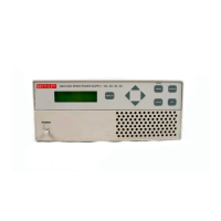
Model 2303 front panel calibration summary
Step* Description
Nominal calibration
signal**
Test connections
0 Output 14V 14V
Figure 2-2
1 Full-scale output voltage 14V
Figure 2-2
2 Full-scale measure 14V
Figure 2-2
3 Full-scale DVM 14V
Figure 2-2
4 5A range output current 1.9A
Figure 2-3
5 5A current limit 1.9A
Figure 2-3
6 5A measure 1.9A
Figure 2-3
7 5mA range output current 4.5mA
Figure 2-4
8 5mA measure 4.5mA
Figure 2-4
 Loading...

