4-16 Troubleshooting Model 2750 Multimeter/Switch System Service Manual
Analog signal switching states
Table 4-5 through Table 4-13 provide switching states of the various relays, FETs, and
analog switches for the basic measurement functions and ranges. These tables can be used
to assist in tracing an analog signal from the input to the A/D multiplexer.
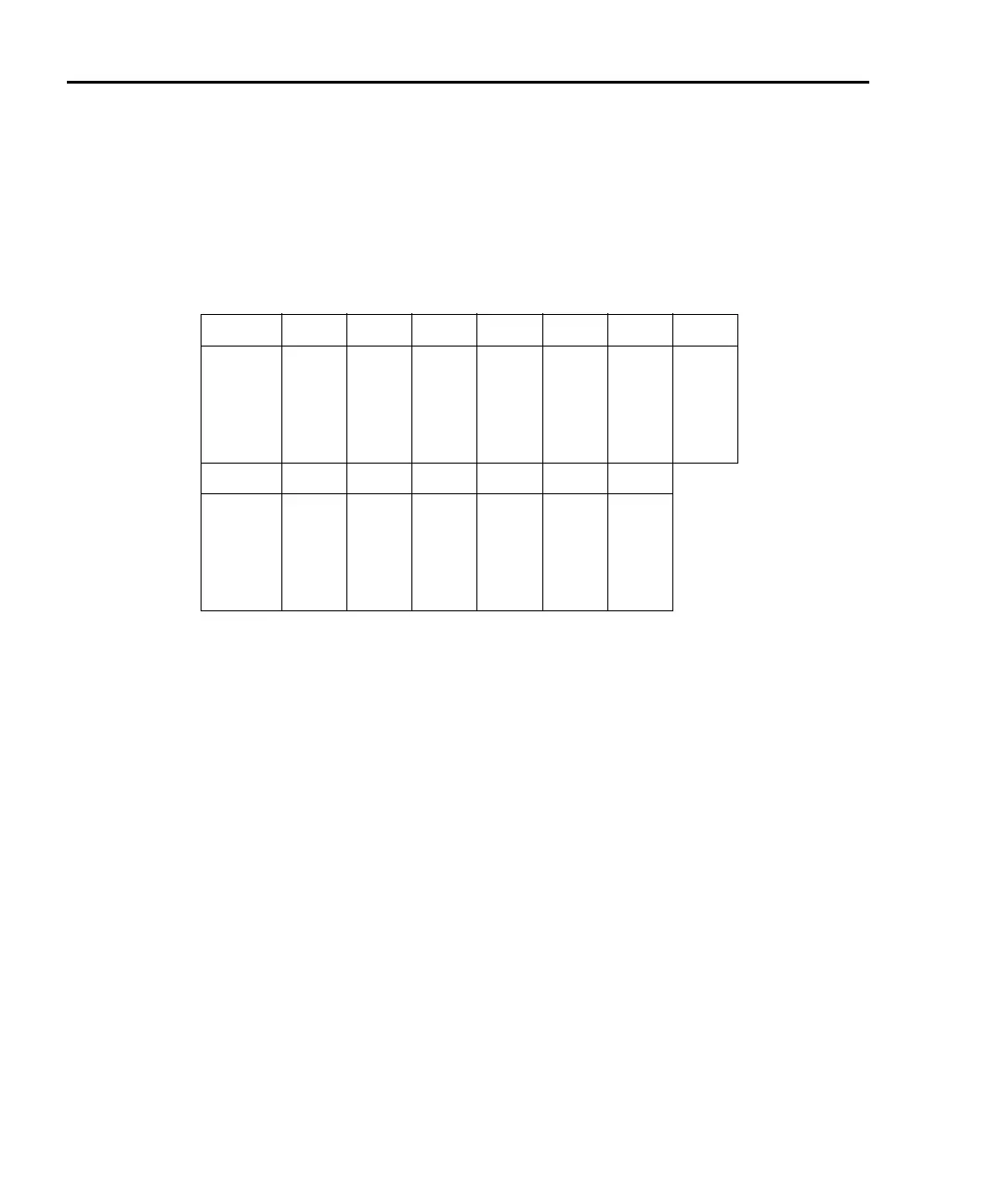
Tab le 4- 5
DCV signal switching
Range Q101 Q102 Q151 Q150 Q114 Q136 Q109
100mV
1V
10V
100V
1000V
ON
ON
ON
OFF
OFF
ON
ON
ON
OFF
OFF
OFF
OFF
OFF
OFF
OFF
OFF
OFF
OFF
OFF
OFF
OFF
OFF
OFF
ON
ON
OFF
OFF
OFF
ON
ON
OFF
OFF
OFF
OFF
OFF
Range K101* Q113 Q104 Q108 Q106 Q148
100mV
1V
10V
100V
1000V
SET
SET
SET
SET
SET
OFF
OFF
OFF
OFF
OFF
ON
ON
ON
OFF
OFF
OFF
OFF
OFF
ON
ON
OFF
OFF
OFF
OFF
OFF
ON
ON
ON
ON
ON
*K101 set states: Pin 8 switched to Pin 7
Pin 3 switched to Pin 4
K101 reset states: Pin 8 switched to Pin 9
Pin 3 switched to Pin 2