1-34 Performance Verification Model 2750 Multimeter/Switch System Service Manual
Verifying frequency
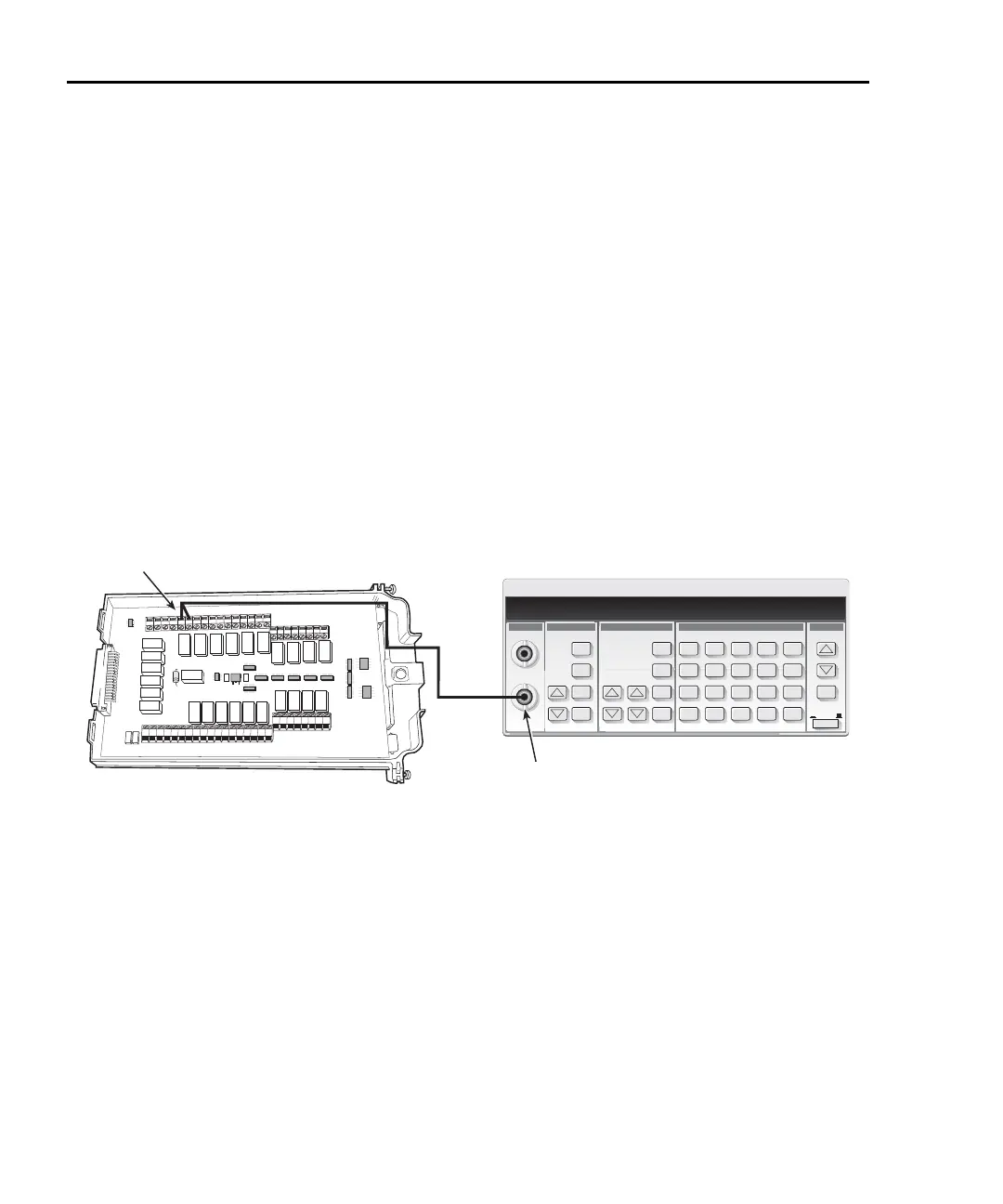
Follow the steps below to verify the Model 2750 frequency function:
1. Connect the function generator to the Model 7700 CH1 H and L INPUT terminals
(Figure 1-17).
2. Install the Model 7700 in Slot 1 of the Model 2750, then turn on the power and
allow the unit to warm up for one hour before proceeding. Be sure the front panel
INPUTS switch is set to the REAR position.
3. Set the function generator to output a 1kHz, 1V RMS sine wave.
4. Select the Model 2750 frequency function by pressing the FREQ key. Close Chan-
nel 1 by pressing the CLOSE key, then ENTER for “SINGLE” channel, and keying
in 101.
5. Verify that the Model 2750 frequency reading is between 0.9999kHz and
1.0001kHz.
Figure 1-17
Connections for Model 7700 frequency verification
HLHL
AMPS
HLHLHLHLHLHL
LO
CH21 CH22 CH11 CH12 CH13 CH14 CH15 CH16
HLHLHLHL
CH17 CH18 CH19 CH20
SENSE
(OHMS, 4 WIRE)
INPUT
(V, 2 WIRE)
HLHLHLHL
CH7 CH8 CH9 CH10
HLHL
HLHL
HLHL
HLHL
INPUT SENSE
CH1 CH2
CH3
CH4
CH5
CH6
CH1
50Ω
Coax
Cable
Model 7700
Function Generator
Function
Output