Model 2750 Multimeter/Switch System Service Manual Performance Verification 1-31
7700 Verification
Verifying temperature
Thermocouple, thermistor, and RTD temperature readings are derived from DC volts and
resistance measurements respectively. For that reason, it is not necessary to independently
verify the accuracy of temperature measurements. As long as the DC volts and resistance
functions meet or exceed specifications, temperature function accuracy is automatically
verified. However, temperature verification procedures are provided below for those who
wish to separately verify temperature accuracy.
Thermocouple temperature
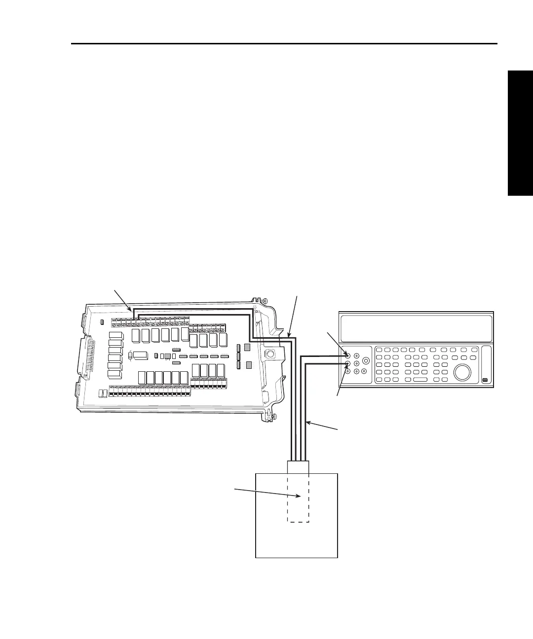
1. Connect the DC voltage calibrator output terminals and ice point reference to the
Model 7700 CH1 H and L INPUT terminals using low-thermal shielded connec-
tions, as shown in Figure 1-16.
Figure 1-16
Connections for Model 7700 thermocouple temperature verification
HLHL
AMPS
HLHLHLHLHLHL
LO
CH21 CH22 CH11 CH12 CH13 CH14 CH15 CH16
HLHLHLHL
CH17 CH18 CH19 CH20
SENSE
(OHMS, 4 WIRE)
INPUT
(V, 2 WIRE)
HLHLHLHL
CH7 CH8 CH9 CH10
HLHL
HLHL
HLHL
HLHL
INPUT SENSE
CH1 CH2
CH3
CH4
CH5
CH6
CH1
Make HI and LO
Connections
in Ice Bath
Ice Bath
Twisted
Thermocouple Wire
Output
HI
Output
LO
Calibrator (Output DC Voltage)
Notes: This setup and reading limits
table does not include errors
from ice point, thermocouple
wire, and connections.
HI and LO connections from
the calibrator and Model 7700
must be electrically isolated
from each other.
Model 7700
Low Thermal
Copper Connection