Model 2750 Multimeter/Switch System Service Manual Performance Verification 1-35
7700 Verification
Verifying ratio and average
Follow the procedure below to verify ratio and average.
CAUTION Exceeding 300V between the 7700 plug-in module INPUT or SENSE H
and L terminals may cause instrument damage.
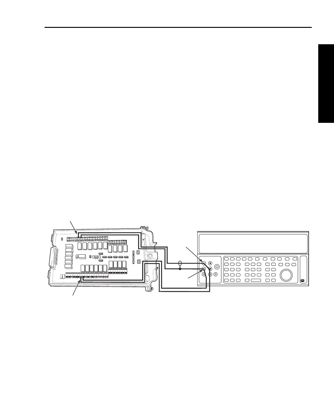
1. Connect the Model 7700 CH1 and CH11 H and L terminals to the DC calibrator, as
shown in Figure 1-18.
2. Install the Model 7700 in Slot 1 of the Model 2750, then turn on the power and
allow the unit to warm up for two hours before proceeding. Be sure the front panel
INPUTS switch is set to the REAR position.
3. Select the Model 2750 DCV function and the 1V range. Close Channel 1 by press-
ing the CLOSE key, then ENTER for “SINGLE” channel, and keying in 101.
4. Select the Model 2750 RATIO function (press SHIFT then RATIO).
5. Set the calibrator output to 1.00000V DC, and allow the reading to settle.
6. Verify that the ratio reading is between 0.9999926 and 1.000074.
7. Press OPEN to open Channel 1.
Figure 1-18
Connections for Model 7700 ratio and average verification
HLHL
AMPS
HLHLHLHLHLHL
LO
CH21 CH22 CH11 CH12 CH13 CH14 CH15 CH16
HLHLHLHL
CH17 CH18 CH19 CH20
SENSE
(OHMS, 4 WIRE)
INPUT
(V, 2 WIRE)
HLHLHLHL
CH7 CH8 CH9 CH10
HLHL
HLHL
HLHL
HLHL
INPUT SENSE
CH1 CH2
CH3
CH4
CH5
CH6
CH1
CH11
Output
HI
Output
LO
DC Voltage Calibrator
Note: Use shielded cables to
minimize noise.
Model 7700