Model 2750 Multimeter/Switch System Service Manual Performance Verification 1-27
7700 Verification
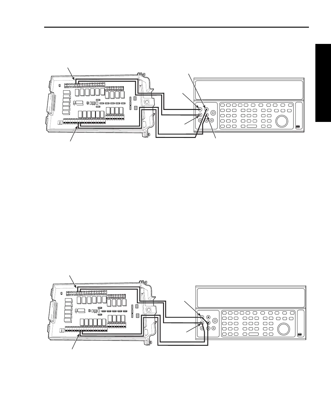
Figure 1-13
Connections for Model 7700 resistance verification (1 to 10M ranges)
7. Source the nominal full-scale resistance values for the 1-10M ranges summa-
rized in Table 1-14, and verify that the readings are within calculated limits.
8. Connect the Model 7700 CH1 and CH11 terminals to the calibrator as shown in
Figure 1-14.
9. Disable external sense on the calibrator.
10. Set the Model 2750 for the 100M range.
11. Source a nominal 100M resistance value, and verify that the reading is within
calculated limits for the 100M range.
12. Press the OPEN key to open Channel 1.
Figure 1-14
Connections for Model 7700 resistance verification (100M range)
HLHL
AMPS
HLHLHLHLHLHL
LO
CH21 CH22 CH11 CH12 CH13 CH14 CH15 CH16
HLHLHLHL
CH17 CH18 CH19 CH20
SENSE
(OHMS, 4 WIRE)
INPUT
(V, 2 WIRE)
HLHLHLHL
CH7 CH8 CH9 CH10
HLHL
HLHL
HLHL
HLHL
INPUT SENSE
CH1 CH2
CH3
CH4
CH5
CH6
CH1
CH11
Output
HI
Output
LO
Resistance Calibrator
Note: Use shielded, low-thermal cables
to minimize noise. Enable or disable
calibrator external sense as indicated
in procedure.
Model 7700
Sense HI
Sense LO
HLHL
AMPS
HLHLHLHLHLHL
LO
CH21 CH22 CH11 CH12 CH13 CH14 CH15 CH16
HLHLHLHL
CH17 CH18 CH19 CH20
SENSE
(OHMS, 4 WIRE)
INPUT
(V, 2 WIRE)
HLHLHLHL
CH7 CH8 CH9 CH10
HLHL
HLHL
HLHL
HLHL
INPUT SENSE
CH1 CH2
CH3
CH4
CH5
CH6
CH1
CH11
Output
HI
Output
LO
Calibrator (Output 2-wire Resistance)
Note: Use shielded cables to minimize
noise. Disable calibrator external
sense mode.
Model 7700