1-18 Performance Verification Model 2750 Multimeter/Switch System Service Manual
Verifying temperature
Thermocouple, thermistor, and RTD temperature readings are derived from DC volts and
resistance measurements respectively. For that reason, it is not necessary to independently
verify the accuracy of temperature measurements. As long as the DC volts and resistance
functions meet or exceed specifications, temperature function accuracy is automatically
verified. However, temperature verification procedures are provided below for those who
wish to separately verify temperature accuracy.
Thermocouple temperature
1. Connect the DC voltage calibrator output terminals to the Model 2750 INPUT
jacks using low-thermal shielded connections. (Use 2-wire connections similar to
those shown in Figure 1-1.) Be sure the INPUTS switch is in the FRONT position.
2. Configure the Model 2750 for °C units, type J temperature sensor, and 0°C simu-
lated reference junction as follows:
a. Press SHIFT then SENSOR, and note the unit displays the temperature units:
UNITS: C. (If necessary, use the cursor and range keys to select °C units.)
b. Press ENTER. The unit displays the sensor type: SENS: TCOUPLE.
c. Make sure that TCOUPLE is displayed, then press ENTER. The unit then dis-
plays the thermocouple type: TYPE: K.
d. Select a type J temperature sensor, then press ENTER. The unit then displays
the reference junction type: JUNC: SIM.
e. Make certain that the simulated reference junction type is selected, then press
ENTER. The unit then displays the current simulated reference junction tem-
perature: SIM: 023.
f. Using the cursor and range keys, set the reference junction temperature to 0°C,
then press ENTER twice to complete the temperature configuration process.
3. Select the temperature function by pressing the TEMP key.
4. Source each of the voltages summarized in Table 1-8, and verify that the tempera-
ture readings are within limits. Be sure to select the appropriate thermocouple type
for each group of readings. (See step 2 above.)
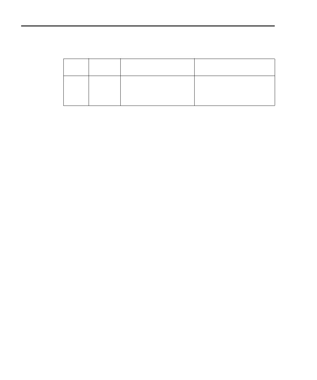
Tab le 1- 7
Limits for Model 2750 dry resistance verification
Range
Nominal
Resistance
Nominal Reading Limits
(1 year, 18°C to 28°C) Recalculated Limits**
1
10
100
1k
1
10
100
1k
0.999860 to 1.000140
9.99860 to 10.00140
99.9820 to 100.0180
0.999510 to 1.000490k
__________ to __________
__________ to __________
__________ to __________
__________ to __________ k
* Enable OCOMP (offset-compensated ohms) when testing 1, 10, 100, and 1k ranges.
** Calculate limits based on actual calibration resistance values and Model 2750 one-year dry circuit resis-
tance accuracy specifications. See “Verification limits.”