Model 2750 Multimeter/Switch System Service Manual Performance Verification 1-17
2750 Verification
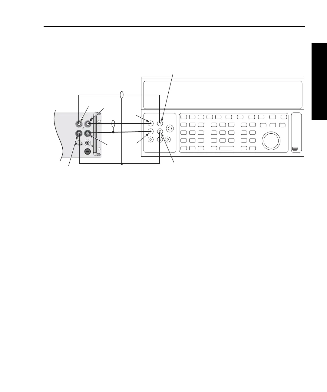
Figure 1-7
Connections for Model 2750 dry circuit resistance verification
2. Set the calibrator for 4-wire resistance with external sense on.
3. Select the Model 2750 4-wire resistance function by pressing the 4 key, then
choose the SLOW integration rate with the RATE key.
4. Select the Model 2750 dry circuit resistance function by pressing SHIFT then
DRYCKT.
5. Set the Model 2750 for the 1 range, and make sure the FILTER is on. Enable
OCOMP (offset-compensated ohms) by pressing SHIFT then OCOMP. (Use
OCOMP for 1, 10, 100, and 1k range verification.) Enable line sync ON by
pressing SHIFT then LSYNC.
NOTE Maximum reading rate for the 1k¾ range is two readings per second.
6. Recalculate reading limits based on actual calibrator resistance values.
7. Source the nominal full-scale resistance values for the 1-1k ranges summarized
in Table 1-7, and verify that the readings are within calculated limits.
Input
HI
Input
LO
Output
LO
Output
HI
Resistance Calibrator
Note: Use low-thermal cables to minimize noise.
Sense
LO
Sense
HI
Sense
LO
Sense
HI
3A, 250V
!
F
500V
PEAK
FRONT/REAR
AMPS
HI
INPUT
LO
SENSE
Ω 4 WIRE
INPUT
350V
PEAK
1000V
PEAK
R
CAT I
Model 2750
Front Panel