1-24 Performance Verification Model 2750 Multimeter/Switch System Service Manual
Verifying DC current
Check DC current accuracy by applying accurate DC currents from the DC current cali-
brator to the input terminals of the Model 7700 and verify that the displayed readings fall
within specified limits.
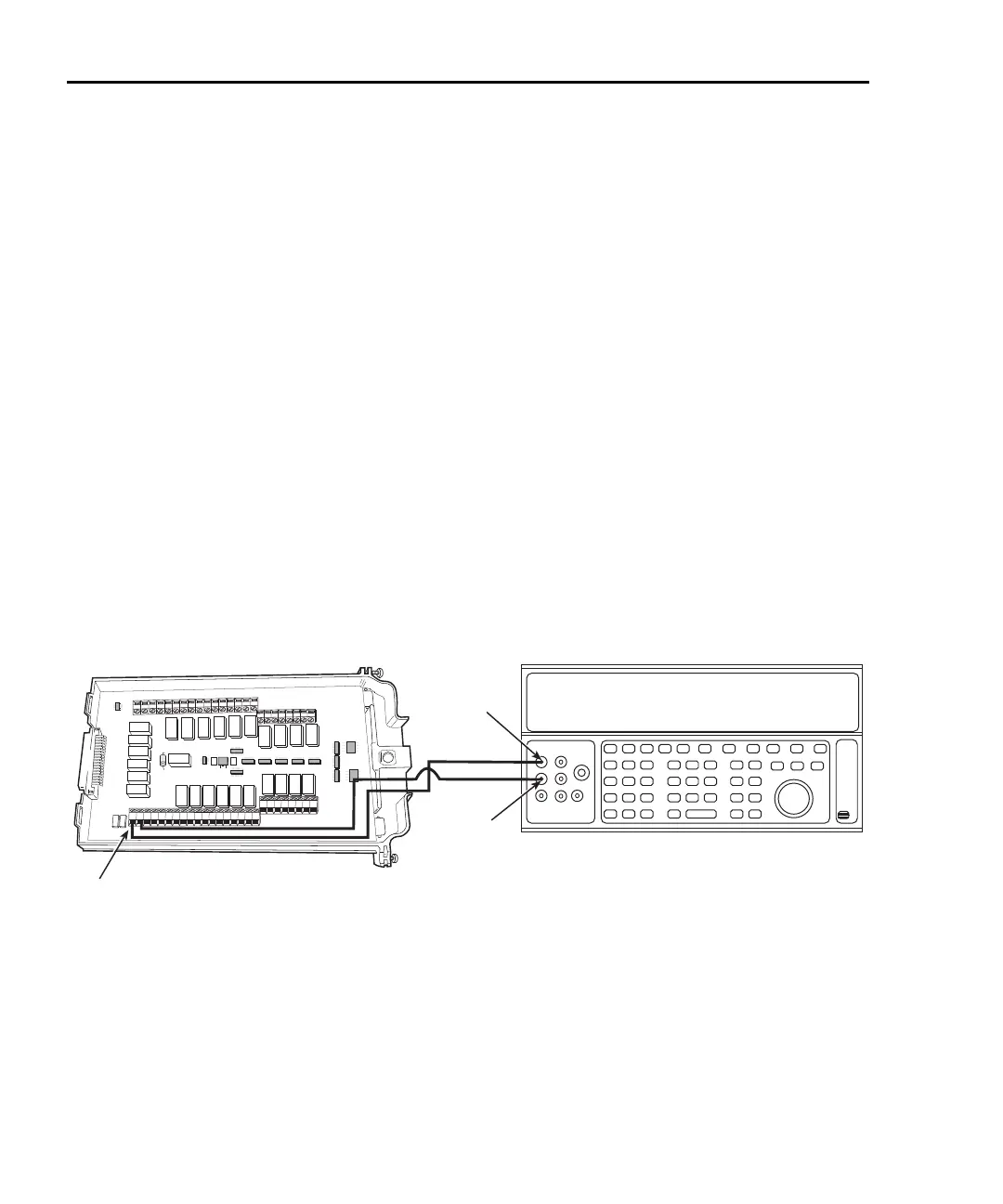
Follow these steps to verify DC current accuracy:
1. Connect the Model 7700 CH21 H and L terminals to the calibrator as shown in
Figure 1-11.
2. Install the Model 7700 in Slot 1 of the Model 2750, then turn on the power, and
allow the unit to warm up for two hours before proceeding. Be sure the front panel
INPUTS switch is set to the REAR position.
3. Select the DC current measurement function by pressing the DCI key.
4. Set the Model 2750 for the 20mA range. Close Channel 21 by pressing the CLOSE
key, then ENTER for “SINGLE” channel, and keying in 121.
5. Source positive and negative full-scale currents for each of the ranges listed in
Table 1-12, and verify that the readings for each range are within stated limits.
6. Press the OPEN key to open Channel 21.
Figure 1-11
Connections for Model 7700 DC current verification
HLHL
AMPS
HLHLHLHLHLHL
LO
CH21 CH22 CH11 CH12 CH13 CH14 CH15 CH16
HLHLHLHL
CH17 CH18 CH19 CH20
SENSE
(OHMS, 4 WIRE)
INPUT
(V, 2 WIRE)
HLHLHLHL
CH7 CH8 CH9 CH10
HLHL
HLHL
HLHL
HLHL
INPUT SENSE
CH1 CH2
CH3
CH4
CH5
CH6
CH21
Output HI
Output
LO
Calibrator (Output DC Current)
Note: Be sure calibrator is set for
normal current output.
Model 7700