Model 2750 Multimeter/Switch System Service Manual Performance Verification 1-13
2750 Verification
Verifying AC current
Check AC current accuracy by applying accurate AC voltage current at specific frequen-
cies from the AC current calibrator to the Model 2750 input, and verify that the displayed
readings fall within specified limits. Follow these steps to verify AC current:
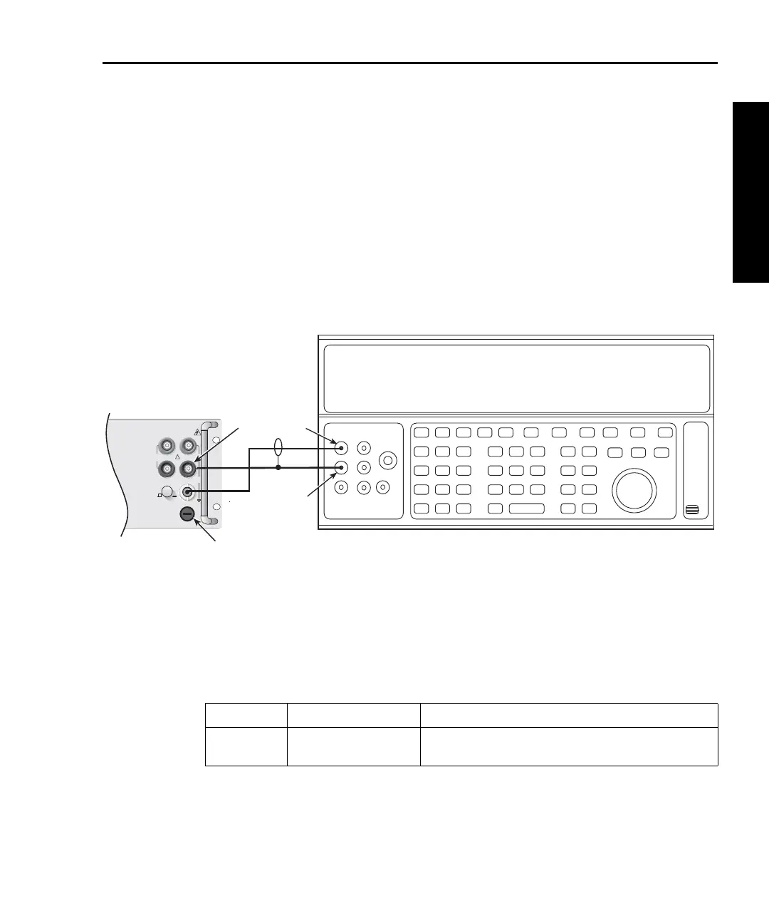
1. Connect the Model 2750 AMPS and INPUT LO jacks to the calibrator as shown in
Figure 1-4. Be sure the INPUTS switch is in the FRONT position.
2. Select the AC current function by pressing the ACI key.
Figure 1-4
Connections for Model 2750 AC current verification
3. Set the Model 2750 for the 1A range.
4. Source 1A and 3A, 1kHz full-scale AC currents as summarized in Table 1-5, and
verify that the readings are within stated limits.
Tab le 1- 5
ACI limits
ACV Range Applied AC Voltage Reading Limits @ 1kHz (1 year, 18°C to 28°C)
1A
3A
1.000000A
3.00000A*
0.99860 to 1.00140A
2.9817 to 3.0183A
* If the Fluke 5725A amplifier is not available, apply 2.2A from the calibrator. Reading limits for 2.2A are
2.1949 to 2.2051A.
Input
LO
Amps
Output
LO
Output
HI
Calibrator (Output AC Current)
!
F
500V
PEAK
FRONT/REAR
AMPS
HI
INPUT
LO
SENSE
Ω 4 WIRE
INPUT
350V
PEAK
1000V
PEAK
R
CAT I
3A, 250V
Model 2750
Front Panel