1-12 Performance Verification Model 2750 Multimeter/Switch System Service Manual
Figure 1-3
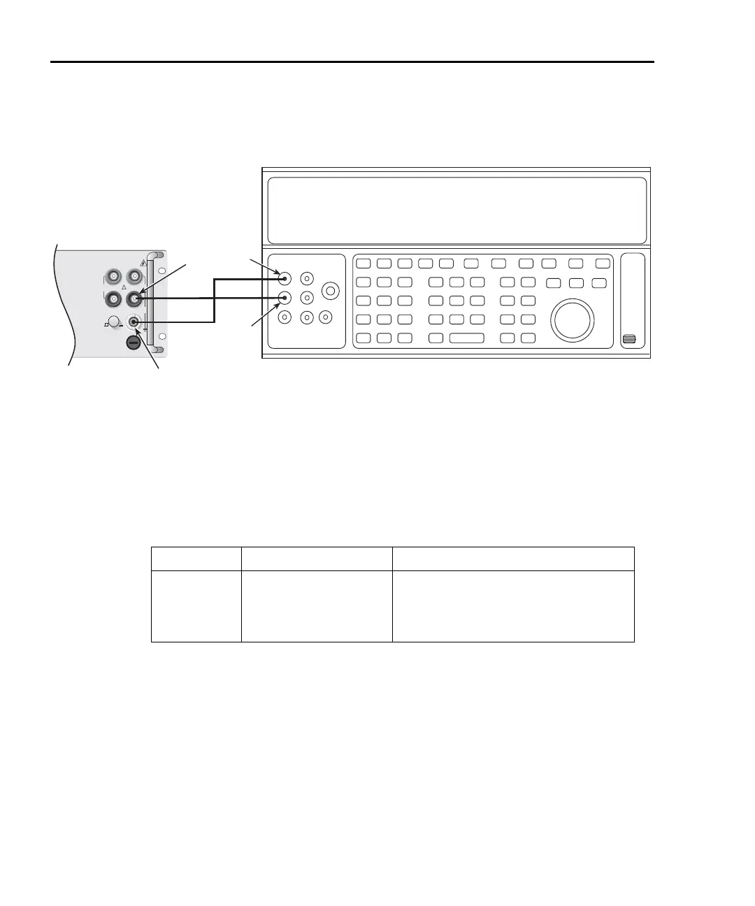
Connections for Model 2750 DC current verification
3. Set the Model 2750 for the 20mA range.
4. Source positive and negative full-scale currents for each of the ranges listed in
Table 1-4, and verify that the readings for each range are within stated limits.
Tab le 1- 4
DCI limits
DCI Range Applied DC Current* Reading Limits (1 year, 18°C to 28°C)
20mA
100mA
1A
3A
20.0000mA
100.0000mA
1.000000A
3.000000A**
19.89960 to 20.01040mA
99.9100 to 100.0900mA
0.999160 to 1.000840A
2.99628 to 3.00372A
*Source positive and negative currents with values shown.
**If the Fluke 5725 amplifier is not available, apply 2.2A from calibrator. Reading limits for 2.2A input
are: 2.197240 to 2.202760A.
Input
LO
Amps
Output
LO
Output
HI
Calibrator (Output DC Current)
Note: Be sure calibrator is set for normal current output.
!
F
500V
PEAK
FRONT/REAR
AMPS
HI
INPUT
LO
SENSE
Ω 4 WIRE
INPUT
350V
PEAK
1000V
PEAK
R
CAT I
Model 2750
Front Panel