Model 2750 Multimeter/Switch System Service Manual Performance Verification 1-9
2750 Verification
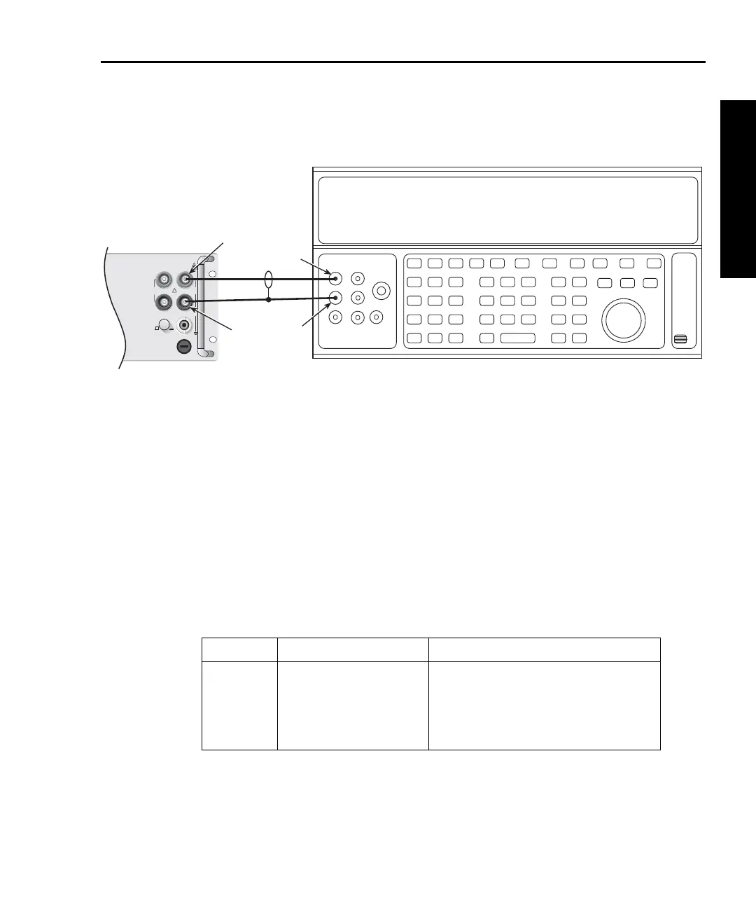
Figure 1-1
Connections for Model 2750 DC volts verification
2. Select the DC volts function by pressing the DCV key, and set the Model 2750 to
the 100mV range.
3. Set the calibrator output to 0.00000mV DC, and allow the reading to settle.
4. Enable the Model 2750 REL mode. Leave REL enabled for the remainder of the
DC volts verification test.
5. Source positive and negative and full-scale voltages for each of the ranges listed in
Table 1-2. For each voltage setting, be sure that the reading is within stated limits.
Tab le 1- 2
DCV reading limits
Range Applied DC Voltage* Reading Limits (1 year, 18°C to 28°C)
100mV
1V
10V
100V
1000V**
100.0000mV
1.000000V
10.00000V
100.0000V
1000.000V
99.9935 to 100.0065mV
0.999963 to 1.000037V
9.99965 to 10.00035V
99.9946 to 100.0054V
999.931 to 1000.069V
*Source positive and negative values for each range.
**Refer to specifications DC note 5 for signal >500V.
Input
HI
Input
LO
Output
LO
Output
HI
Calibrator (Output DC Voltage)
Note: Use shielded, low-thermal cables
for 100mV and 1V ranges.
!
F
500V
PEAK
FRONT/REAR
AMPS
HI
INPUT
LO
SENSE
Ω 4 WIRE
INPUT
350V
PEAK
1000V
PEAK
R
CAT I
3A, 250V
Model 2750
Front Panel